Bemco Machine Works Ltd. · Baja SAE, Western University
Manufacturing Intern
Bemco Machine Works LTD. · Mississauga, ON ·
May 2025 – Aug. 2025, May 2026 – Aug. 2026
Produced dimensioned CAD models and manufacturing drawings from existing physical
components in SolidWorks, reconstructing geometry, tolerances, and GD&T callouts for
legacy parts lacking documentation; drawings were released to production and used to
manufacture parts.
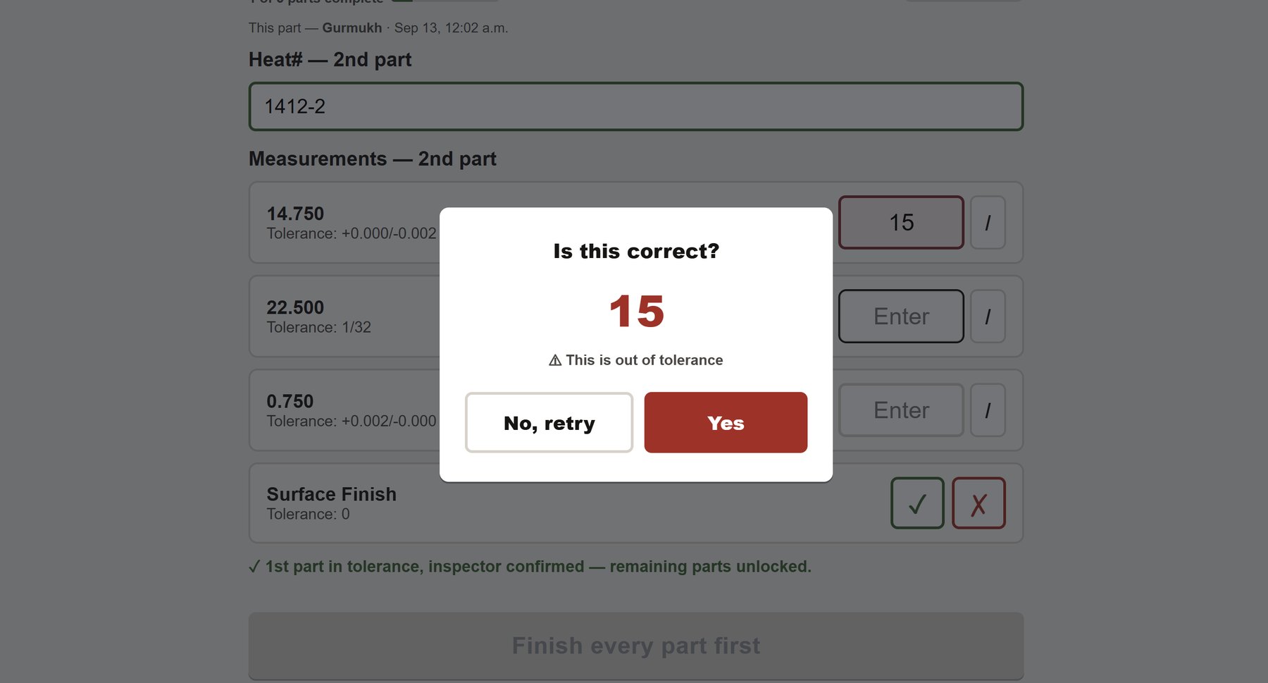
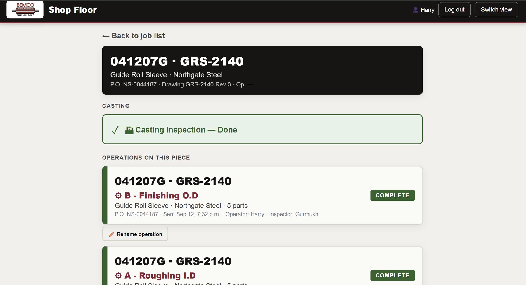
Designed and deployed the shop’s production quality-control system, replacing a
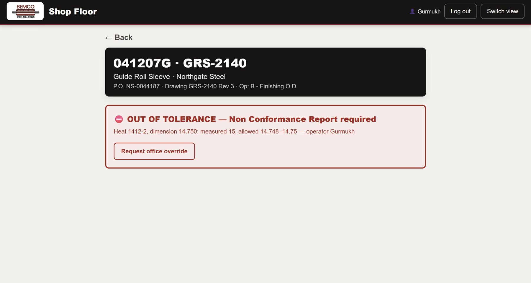
paper-based inspection workflow with enforced dimensional verification that hard-stops a
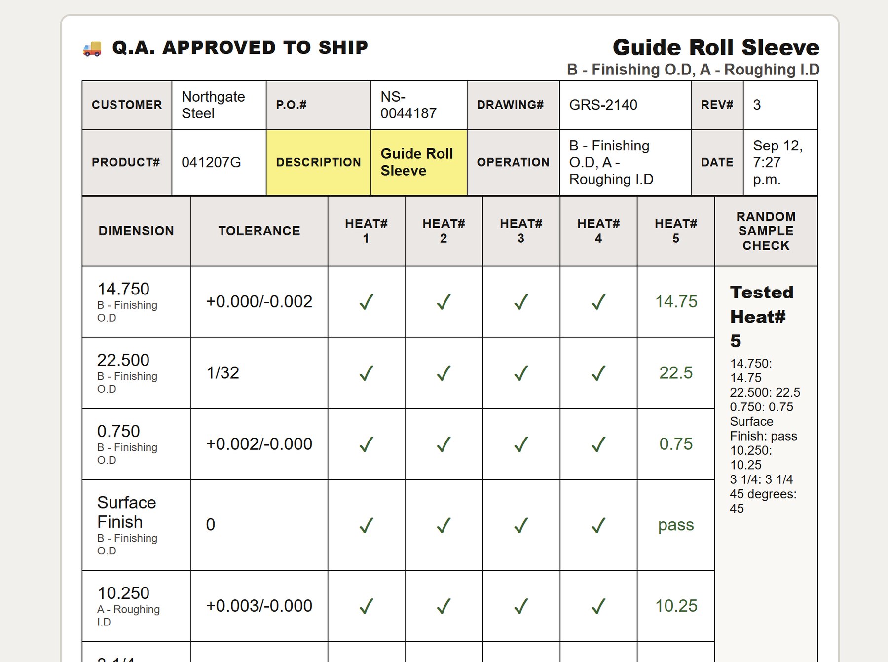
job when a reading falls out of spec, staging inspection from casting to first-article to
QA-approved-to-ship with blind re-measurement; used daily by 6 machinists across
~10 work orders per day.
Operated manual lathes independently across the full job scope — interpreting
drawings, planning operation sequence, selecting tooling and speeds/feeds, and performing
in-process dimensional inspection to hold specified tolerances.
Manufactured precision components on CNC mills and lathes, frequently operating
2–3 machines concurrently and holding tolerances as tight as ±0.001 in.;
proposed revised CAD designs of existing components to improve manufacturability and reduce
machining operations.
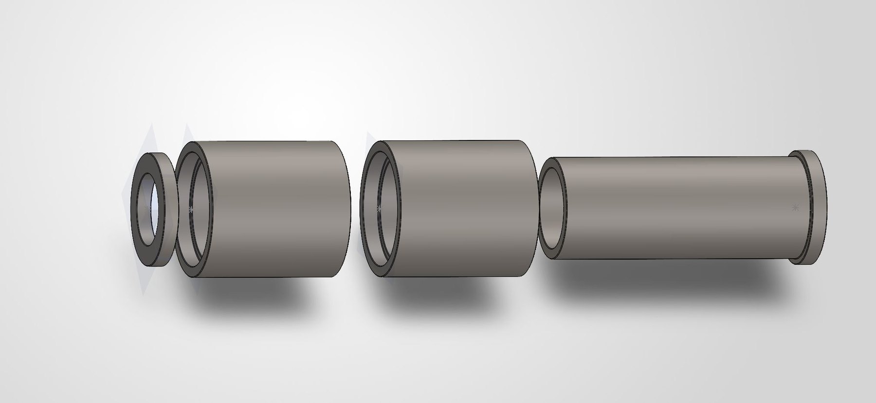
Bemco manufactures rolls for the steel mill industry and originated the sleeved roll design.
A solid roll wears out where the impact lands, so Bemco redesigns it as a hub carrying one or two
sleeves. A worn sleeve can be reversed to use its unworn side, and the two sleeves can be swapped.
Two sleeves with two usable sides each gives four times the service life of a solid roll.
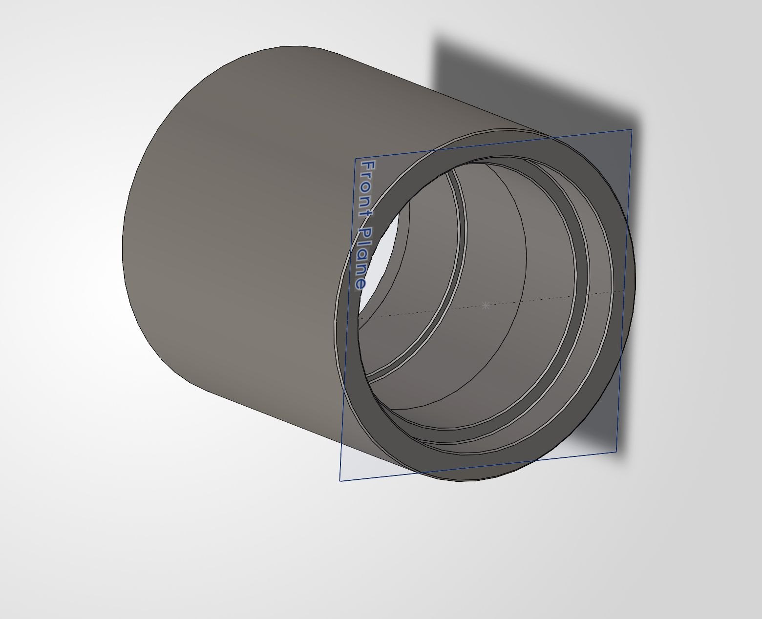
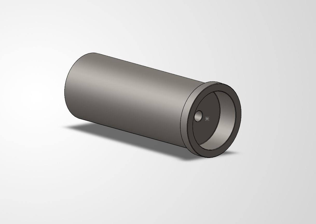
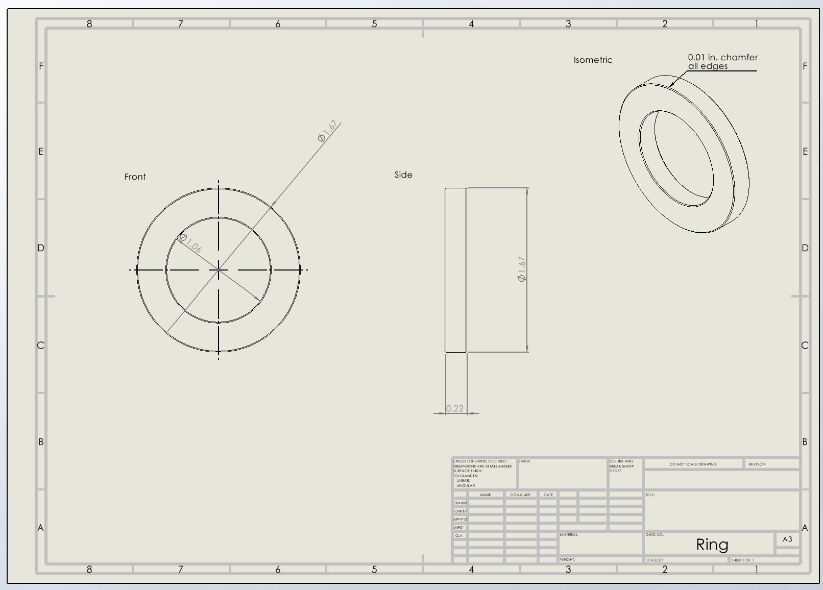
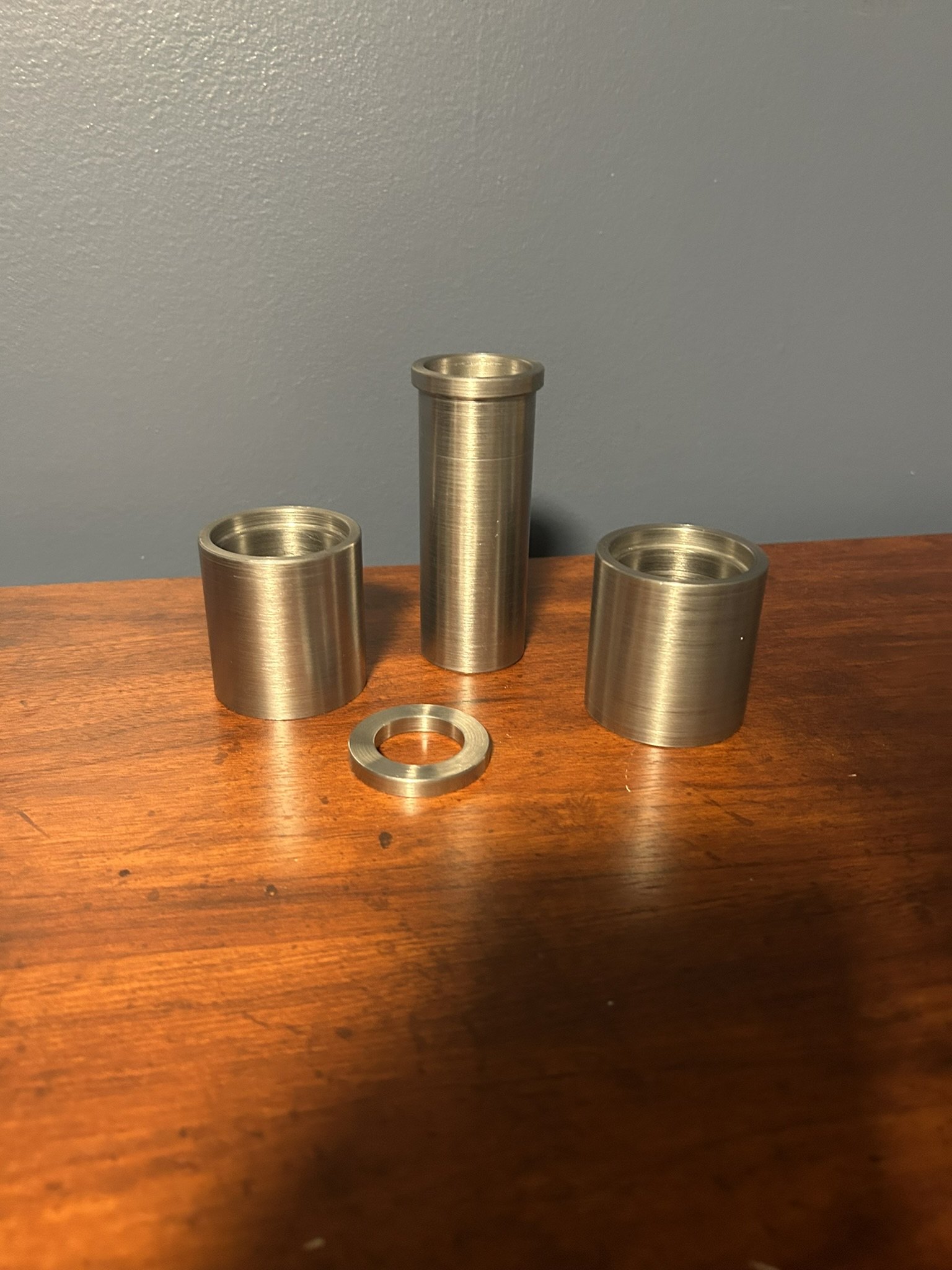
I built scaled training versions of the full two-sleeve assembly. I modelled the hub, sleeves
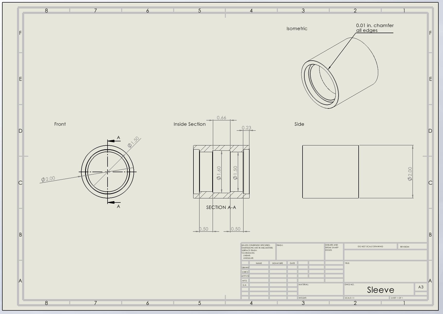
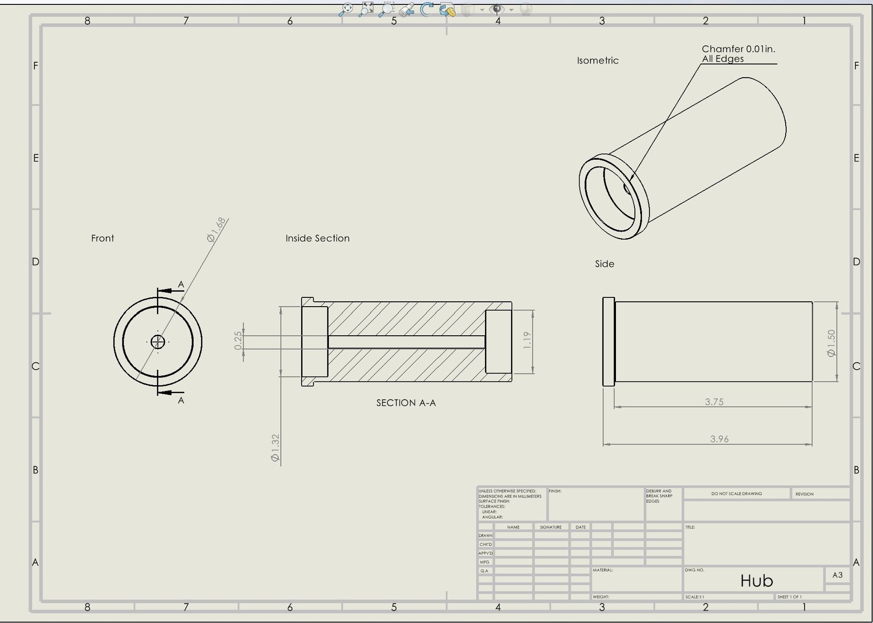
and ring in SolidWorks, produced dimensioned drawings with section views and chamfer callouts,
machined the parts on manual and CNC lathes, and assembled them to check fit.
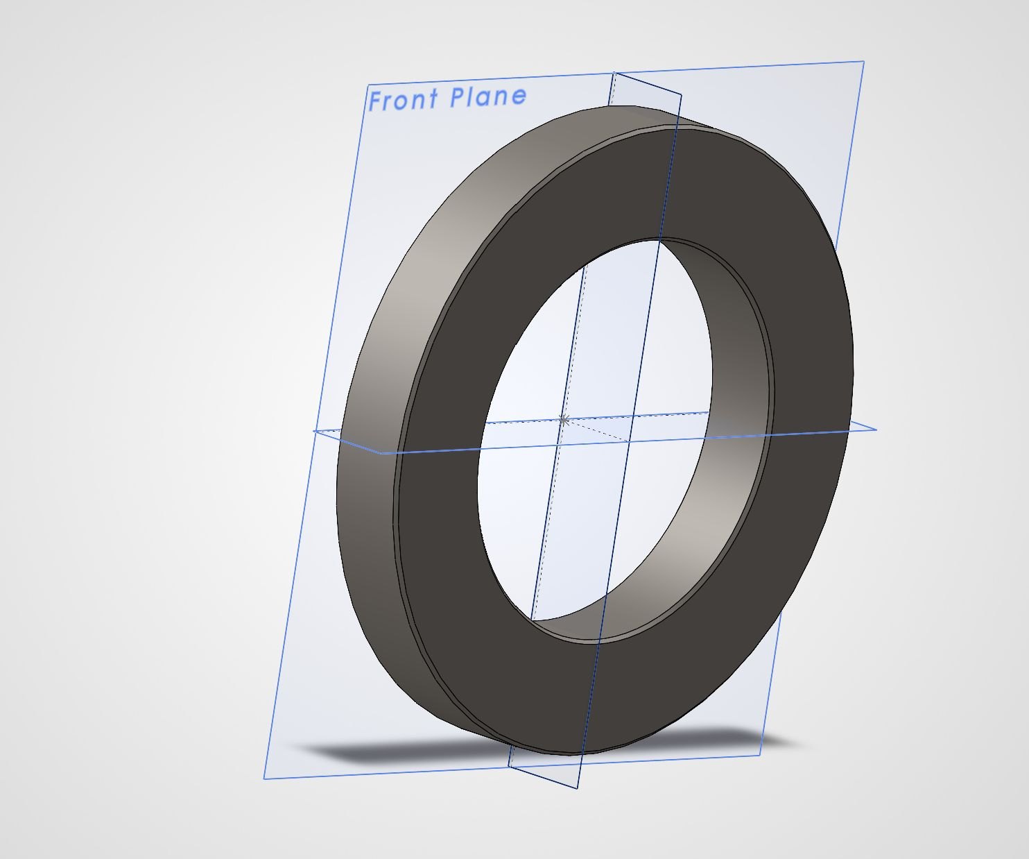
SolidWorks models and exploded assembly
RingHub, sectioned to show the boreSleeveExploded assembly — hub, two sleeves and ring
Manufacturing drawings
Ring — front, side and isometric with chamfer calloutHub — section A-A through the boreSleeve — inside section with wall thicknesses
Setup and machining
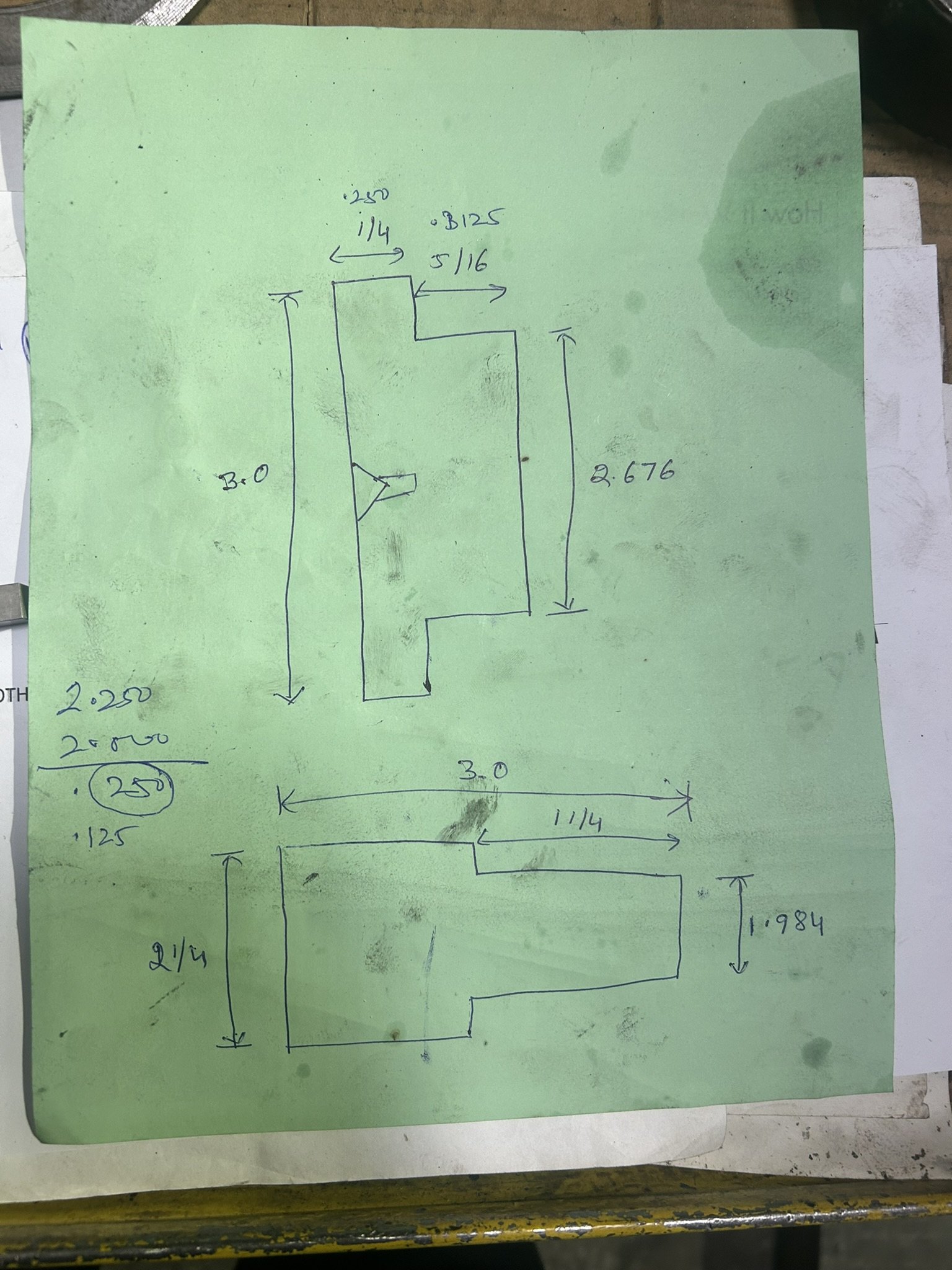
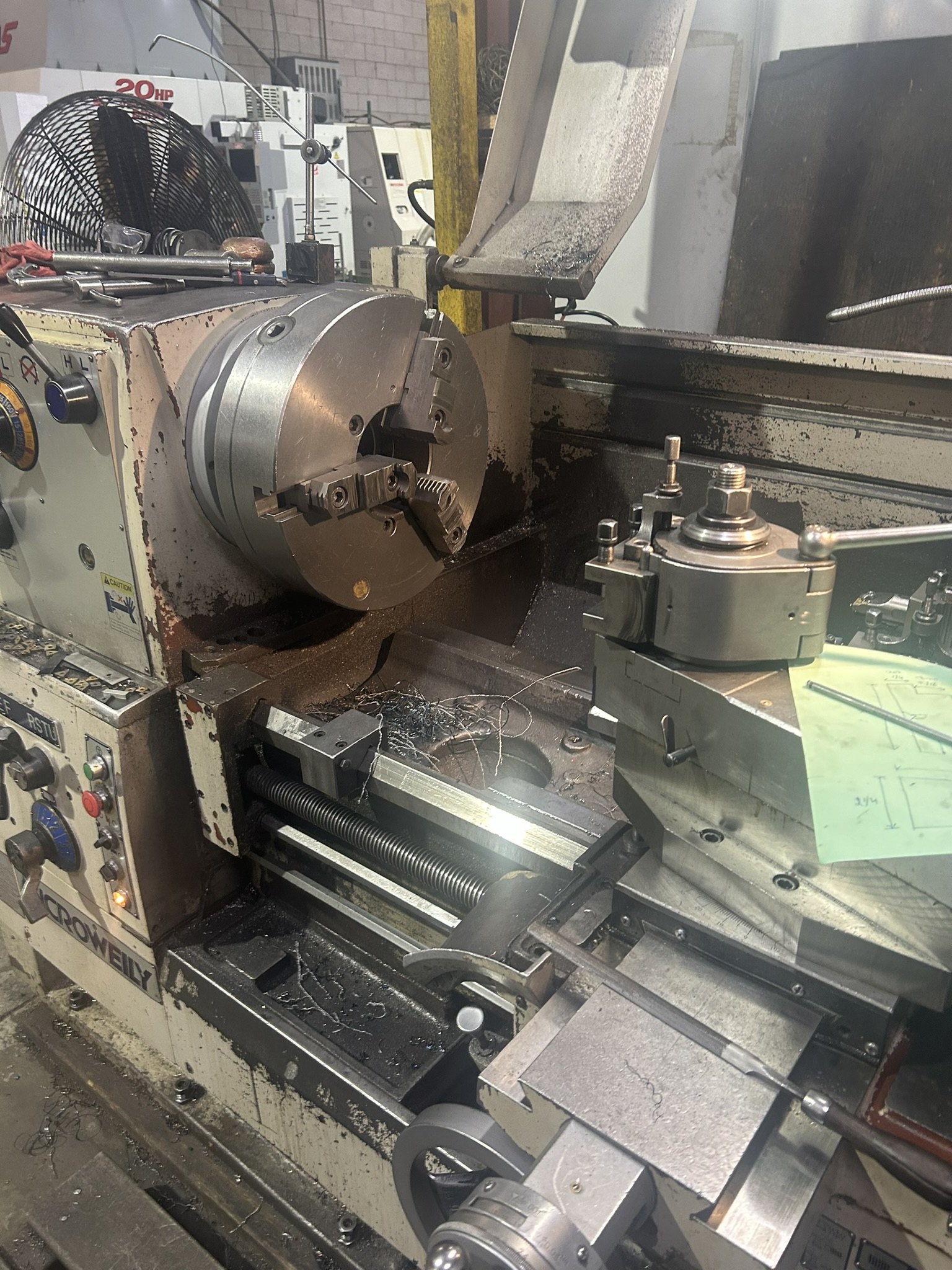
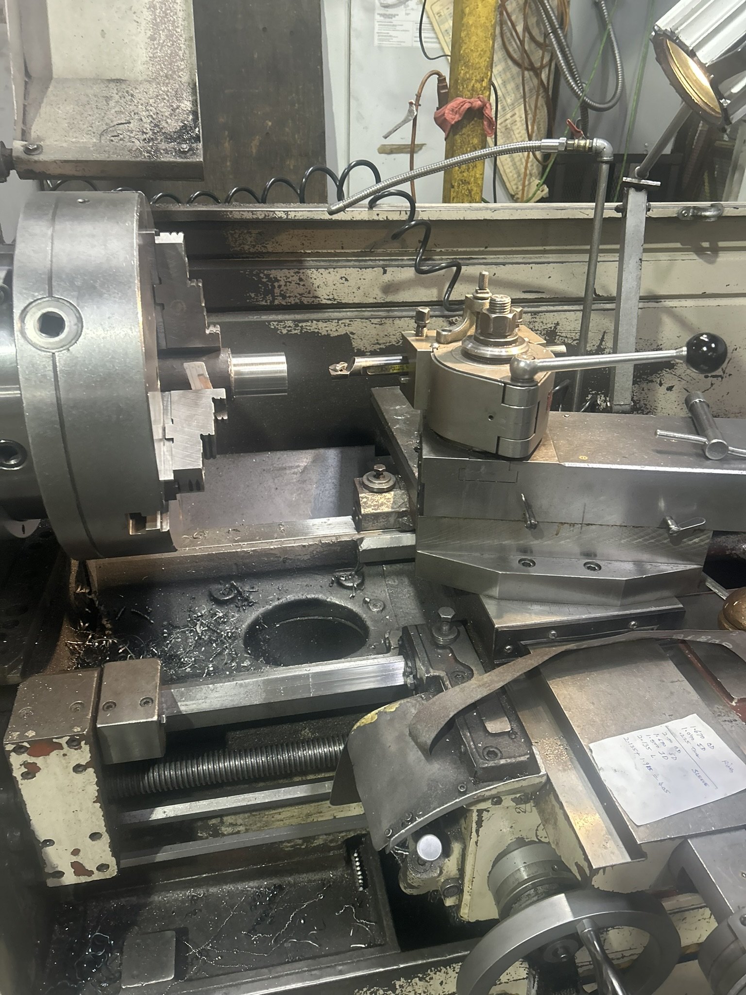
Working the cut on paper. Depth of cut taken from the diameter difference, taped to the machineManual lathe setup, three-jaw chuckTurning in progressBar stock
Machined and assembled
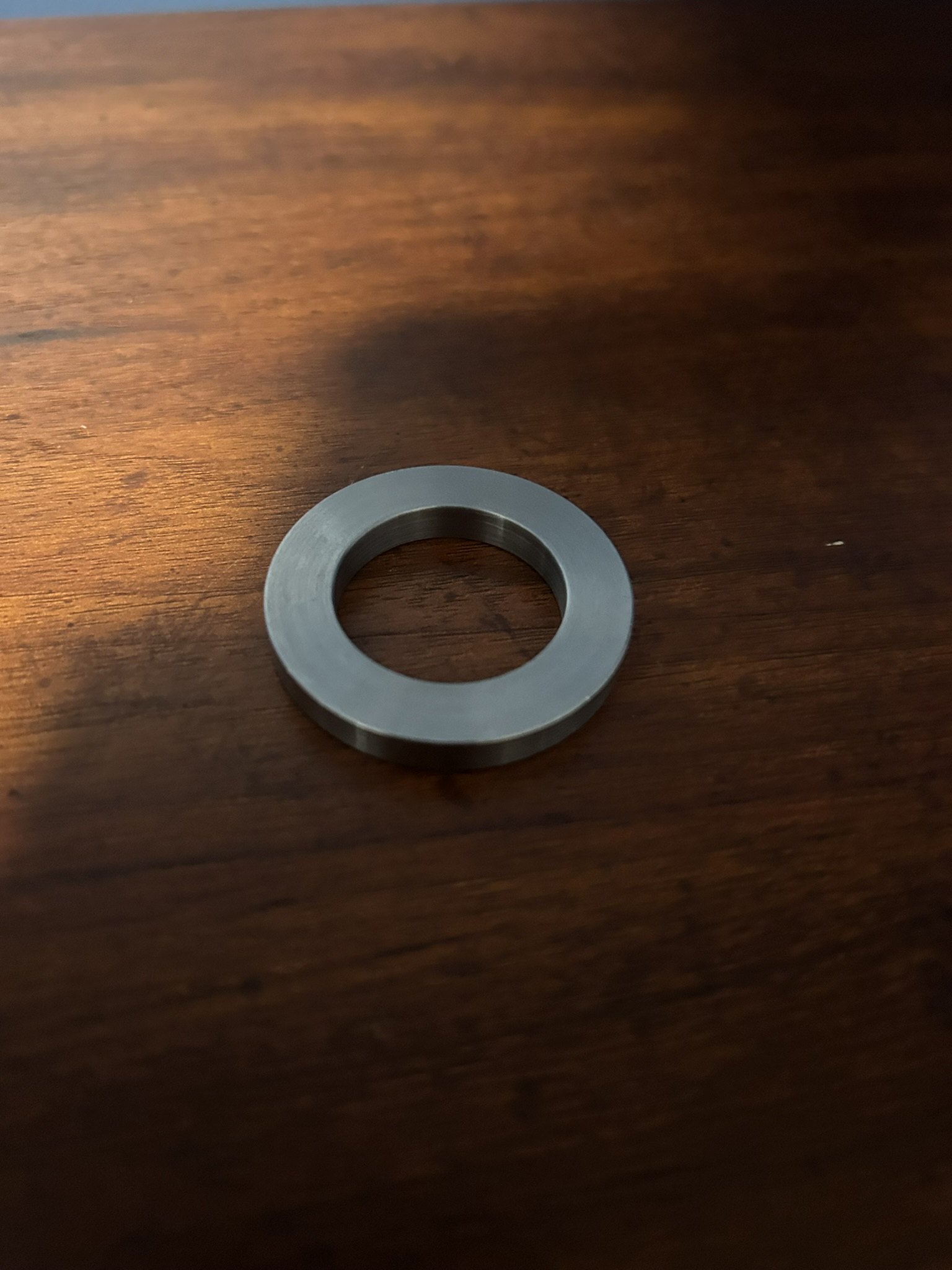
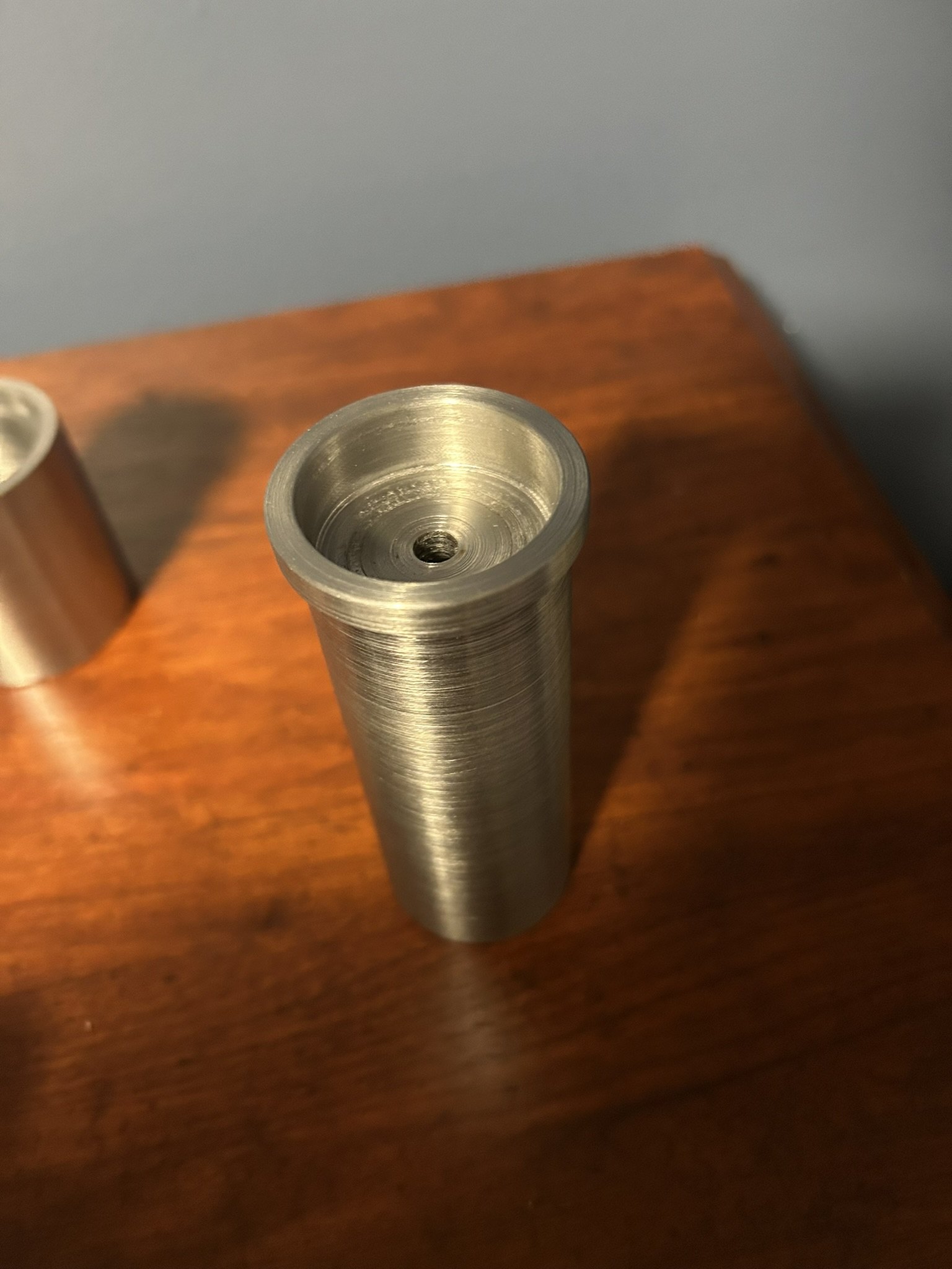
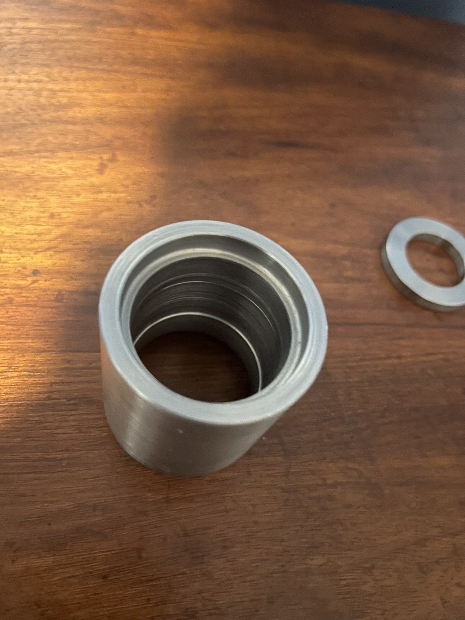
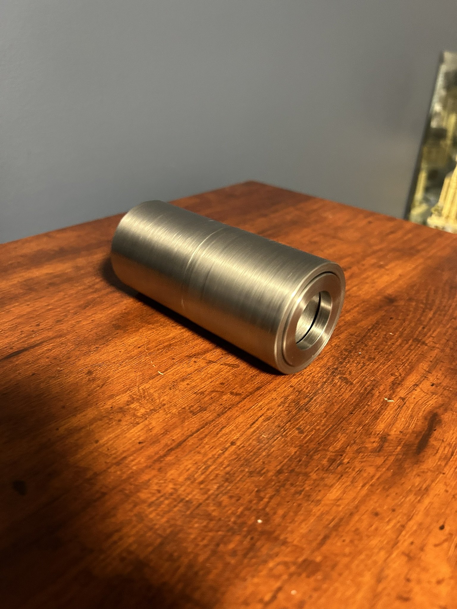
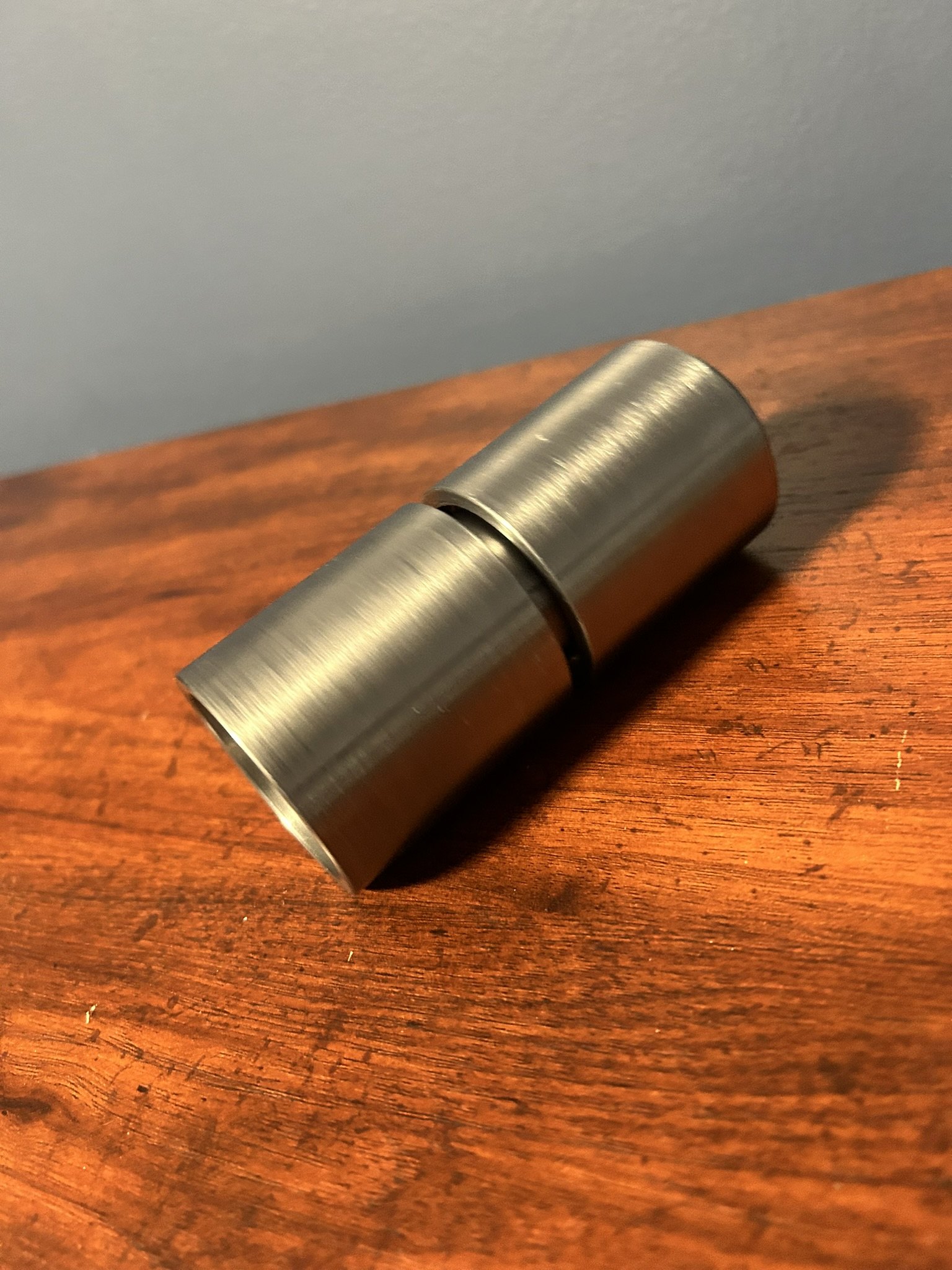
Hub, sleeves and ring togetherRingHub — through bore and stepped diameterSleeve and ringSleeve, outside diameter finishSleeve, second viewHub standing on the bore endAssembled — sleeves seated on the hub
Reverse engineering
From Part to Drawing
Dimensional inspection · SolidWorks · GD&T
These parts I made had no drawings. They were legacy components, and the only record of the
geometry was the part itself. I measured them and rebuilt them in SolidWorks including geometry,
tolerances and GD&T callouts.
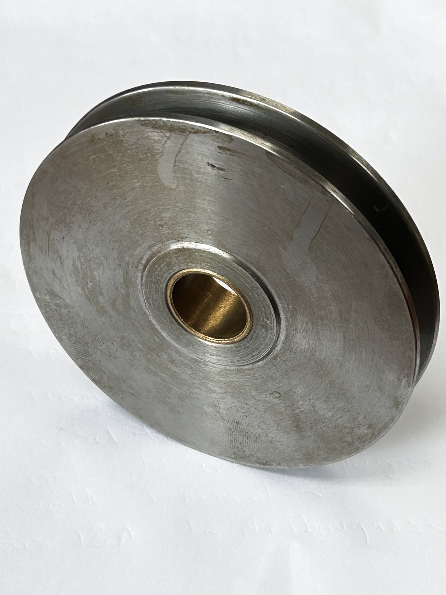
Each pair below is the same component.
The physical part on the left, the model I built from measuring it on the right.
Drag or hover across each image to wipe between the physical part and the model built from measuring it.
↔
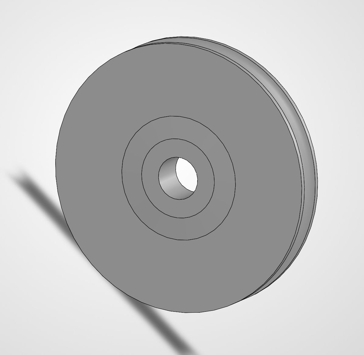
The partMy model
Disc. A turned disc with a central boss. Diameters, boss height and bore measured off the part, then rebuilt.
↔
The partMy model
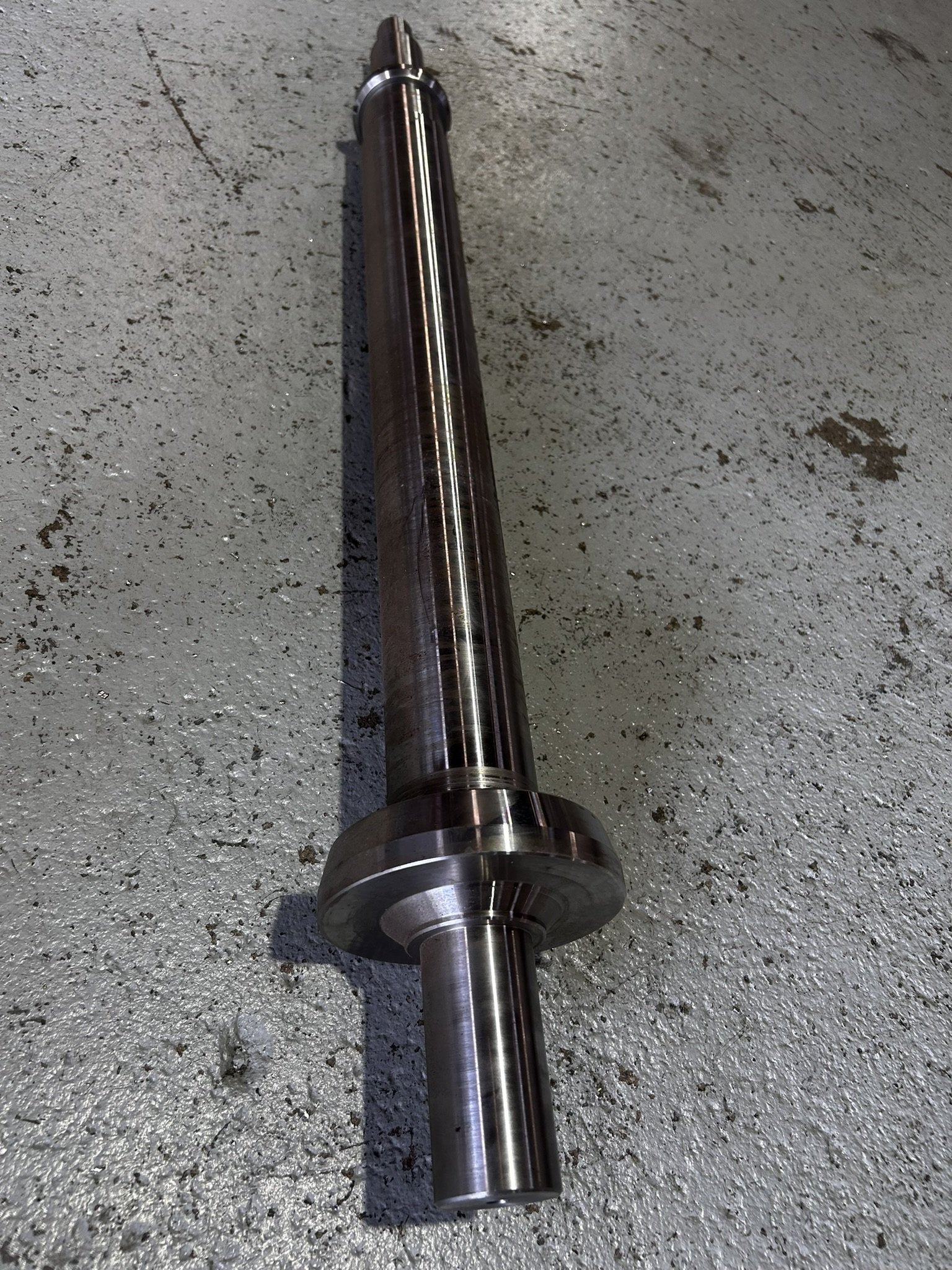
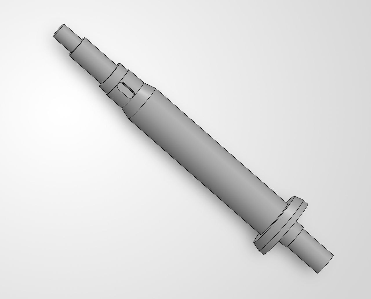
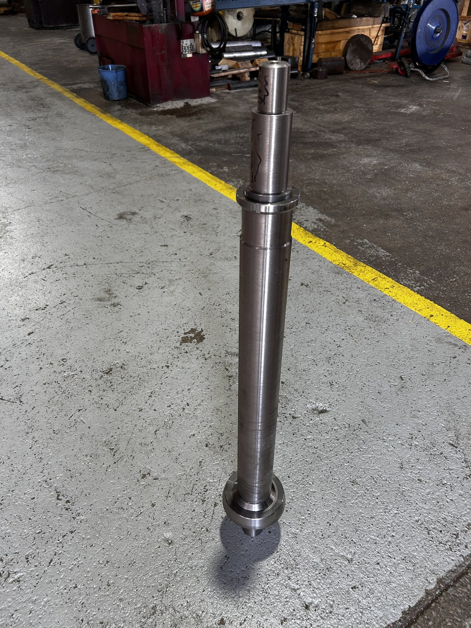
Stepped shaft. Five diameters, a keyway and a shoulder flange. Every step and transition measured and reproduced.
↔
The partMy model
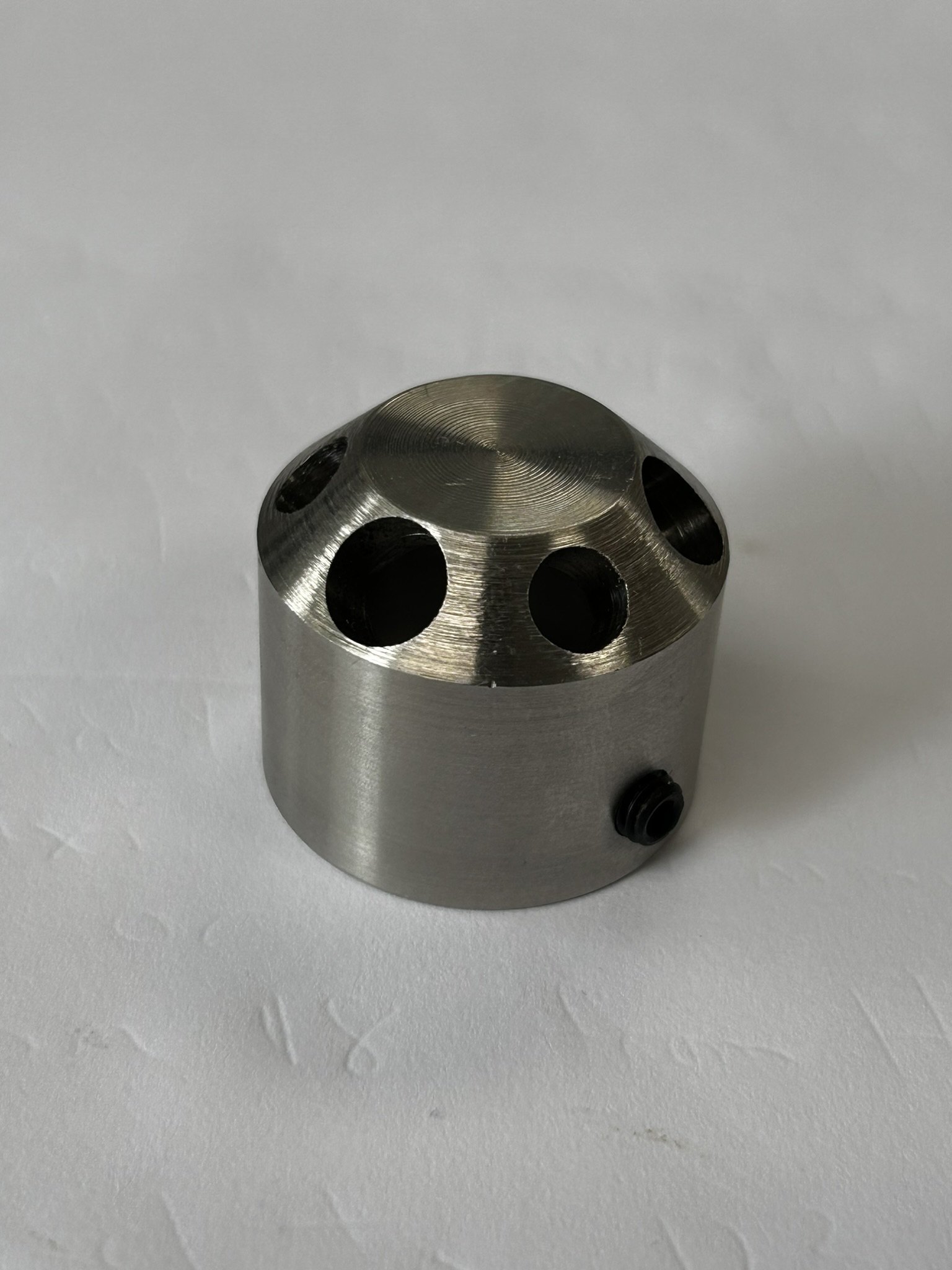
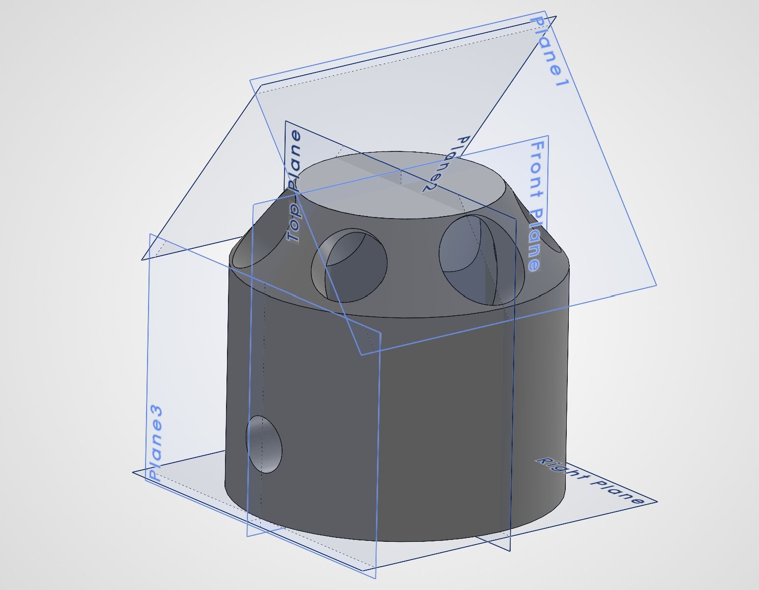
Cross-drilled block. Hex body with angled cross-drilled bores. Rebuilt on multiple reference planes to place the holes correctly.
↔
The partMy model
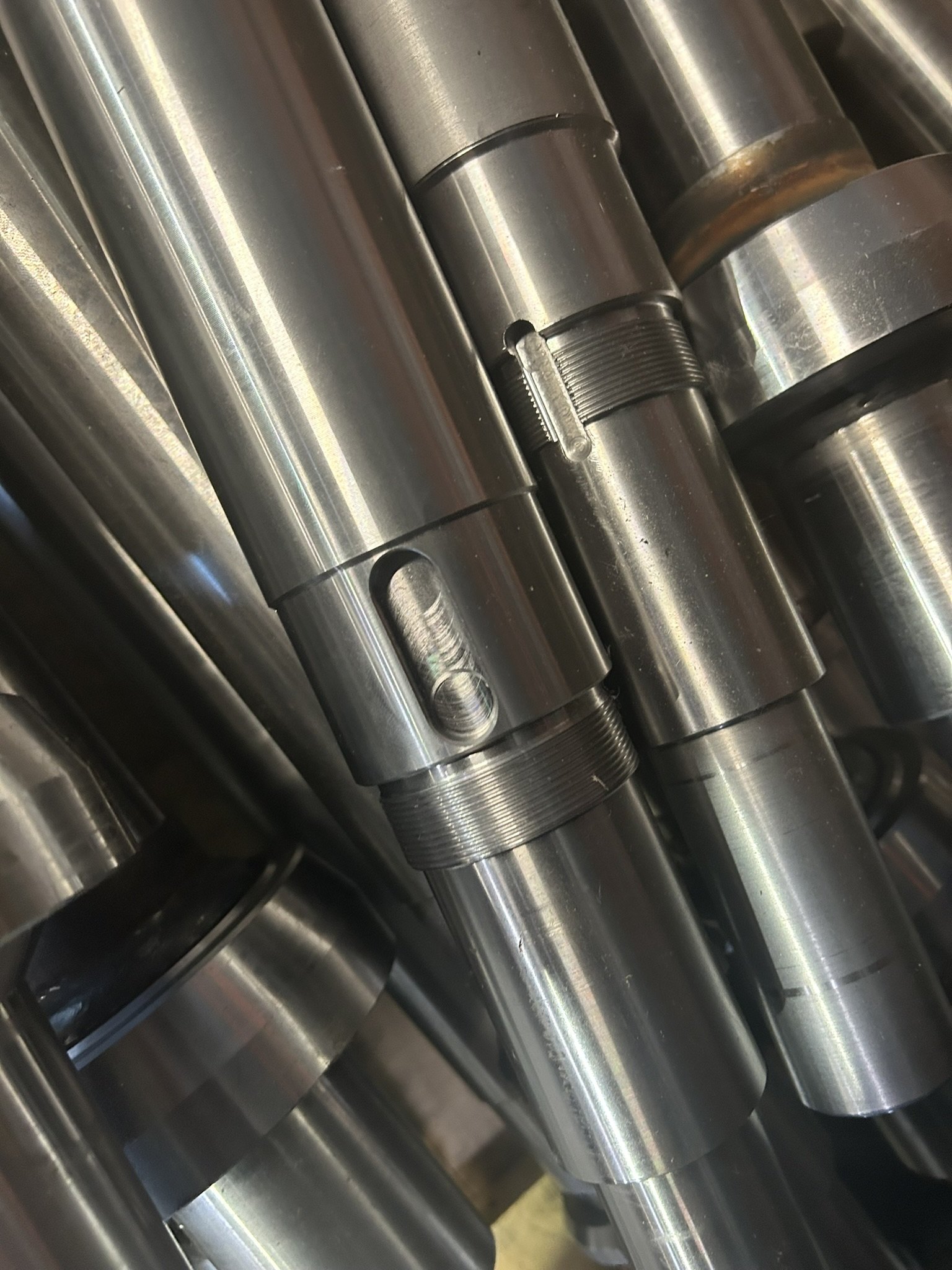
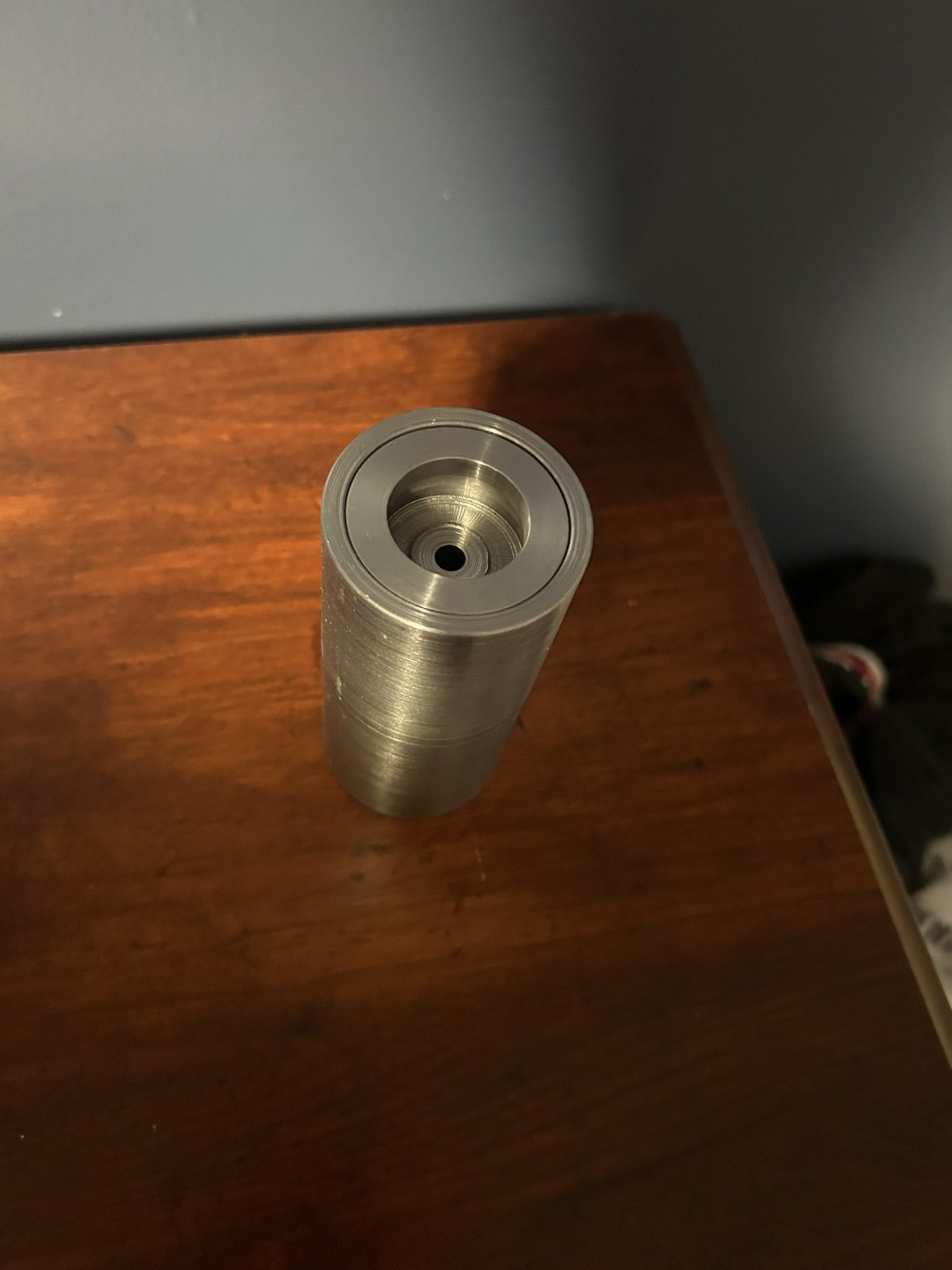
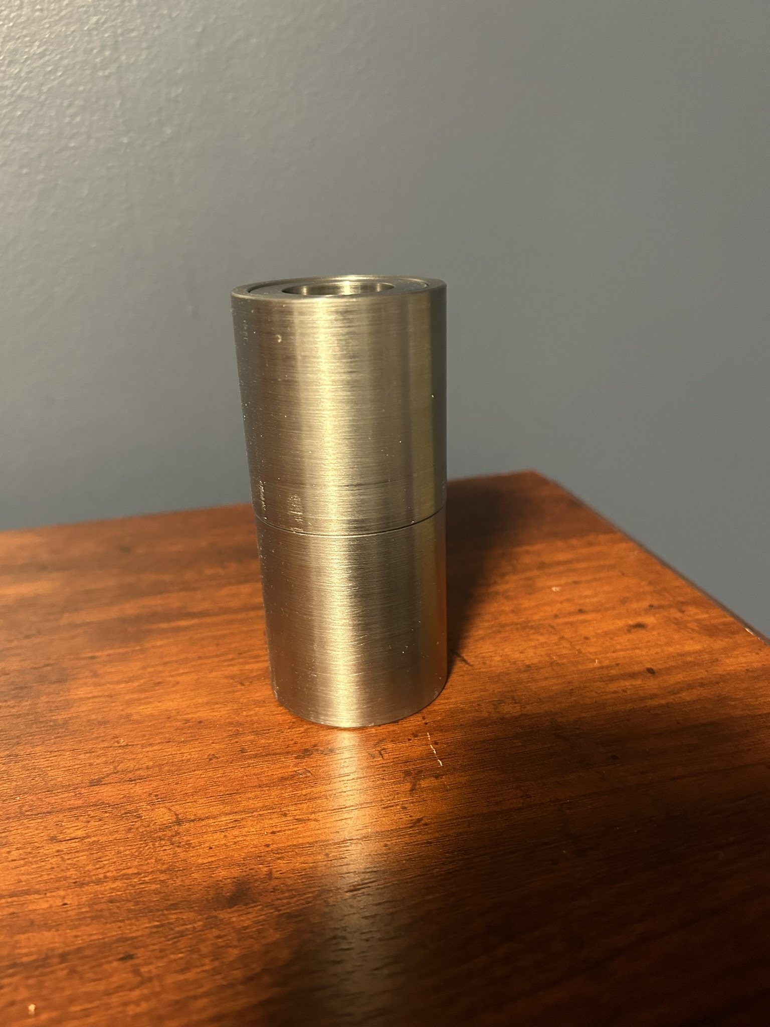
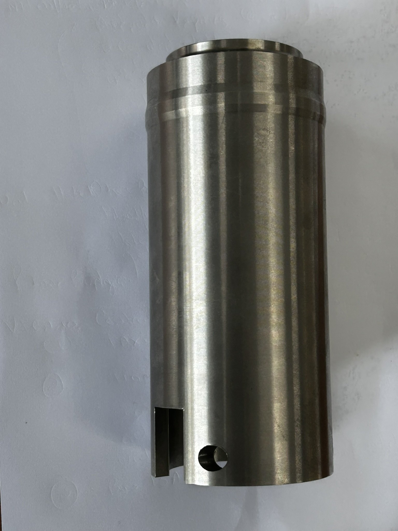
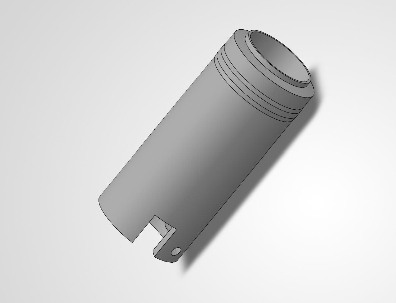
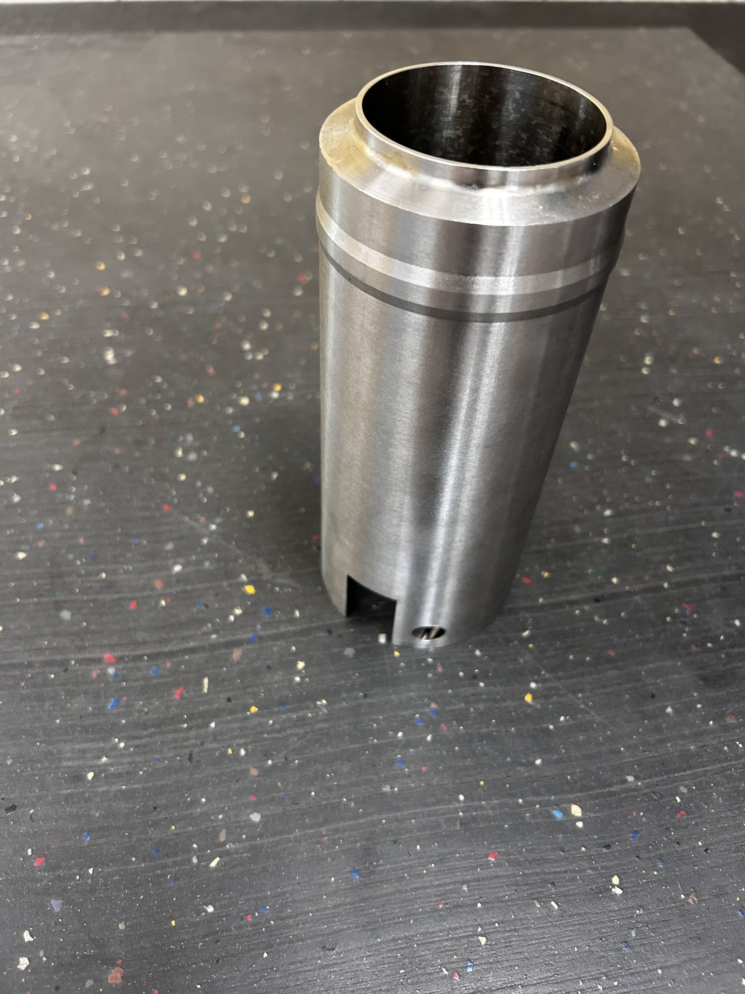
Slotted cylinder. Threaded end, internal bore and an open slot. Wall thickness and slot position taken from the part.
↔
The partMy model
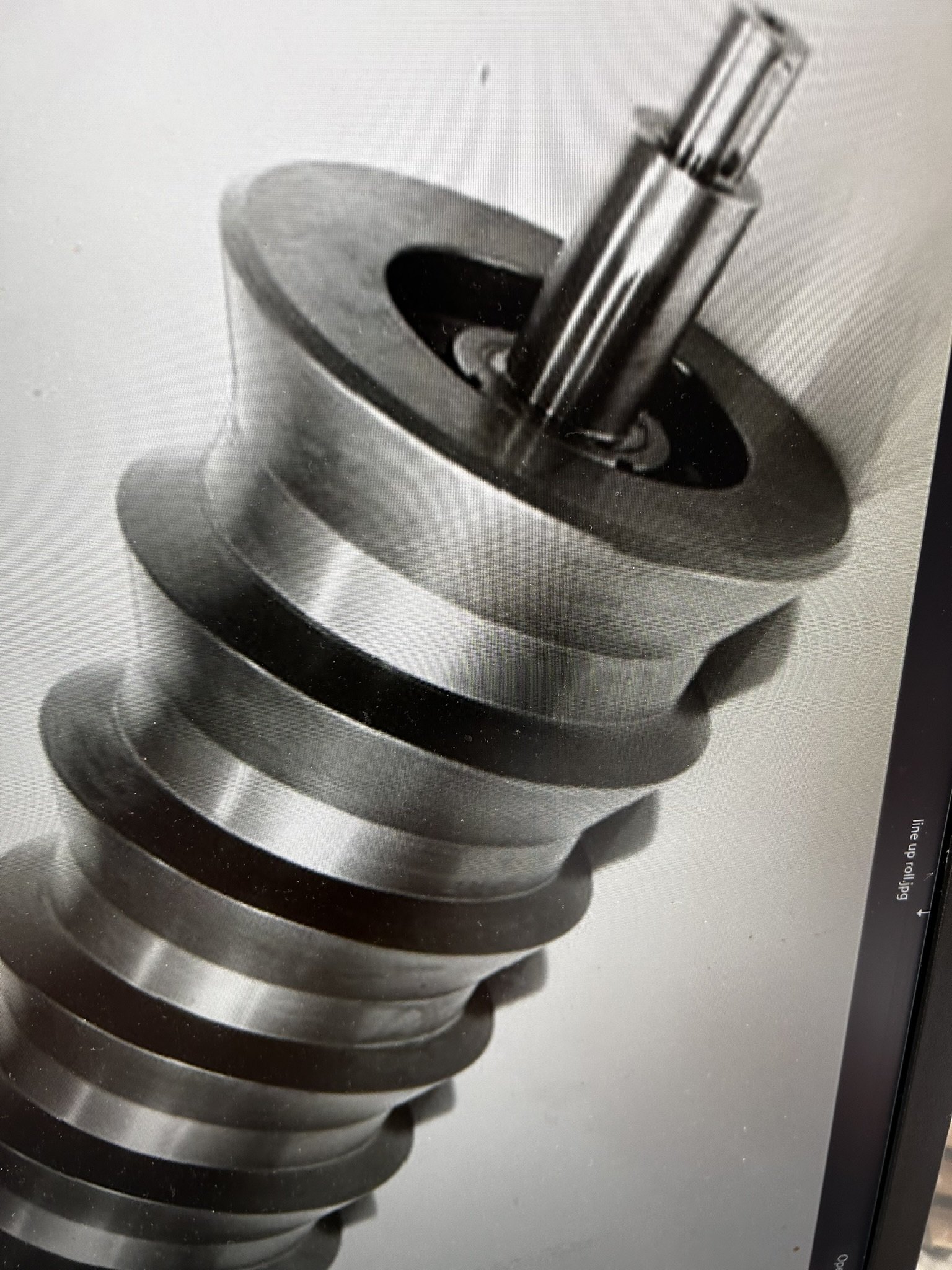
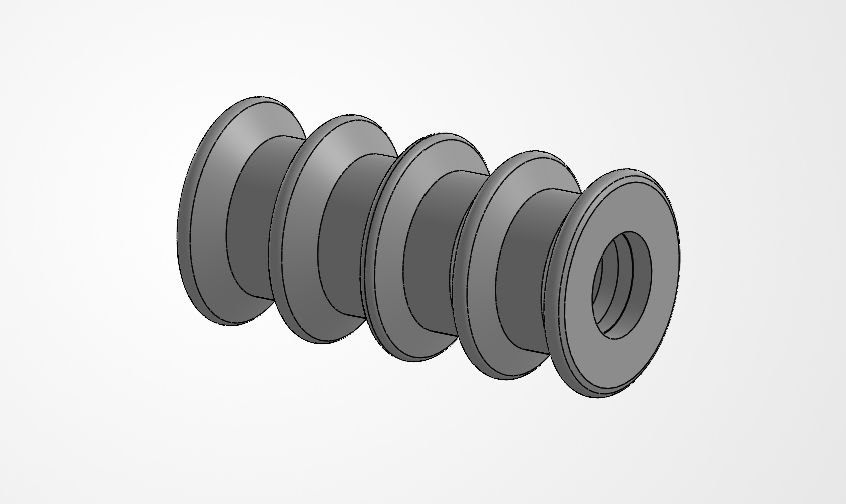
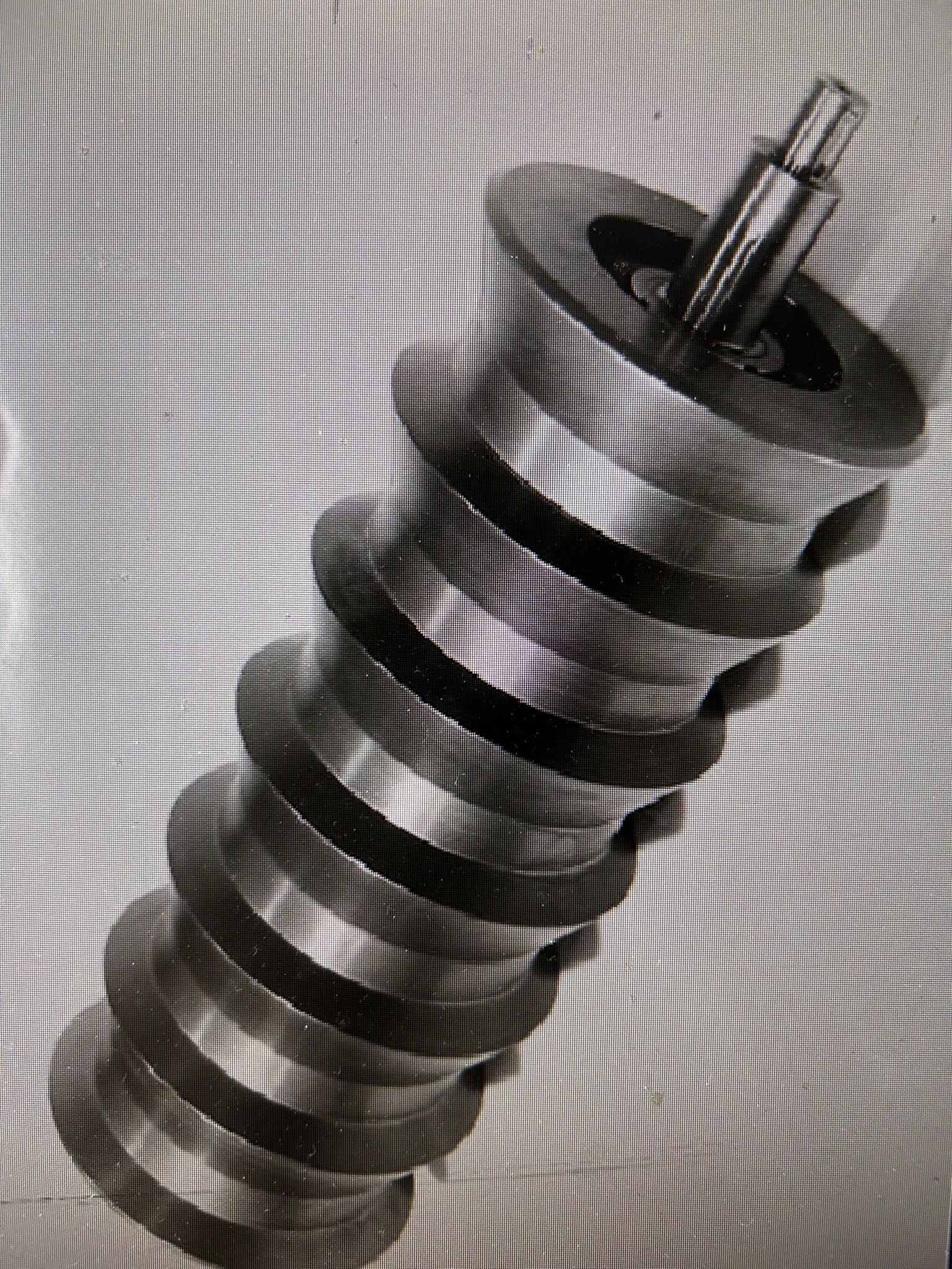
Multi-groove spool. Five grooves at matched pitch. Groove profile and spacing measured, then modelled as a repeating feature.
Further views of the originals
Slotted cylinder — bore and internal stepMulti-groove spool — groove profileStepped shaft — full length
Manufacturing
Machining from Drawings
Manual and CNC lathe · Tolerances to ±0.001 in.
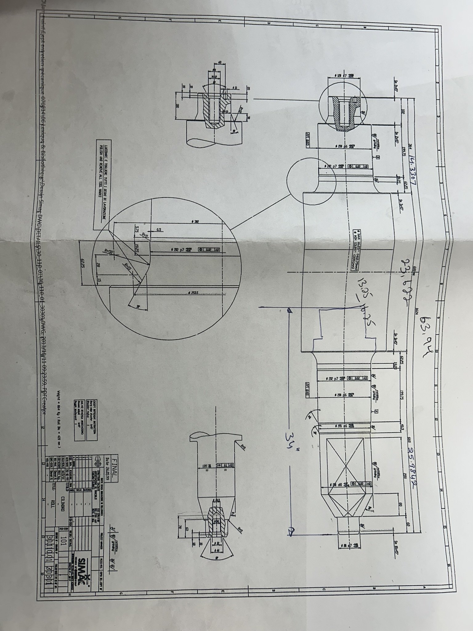
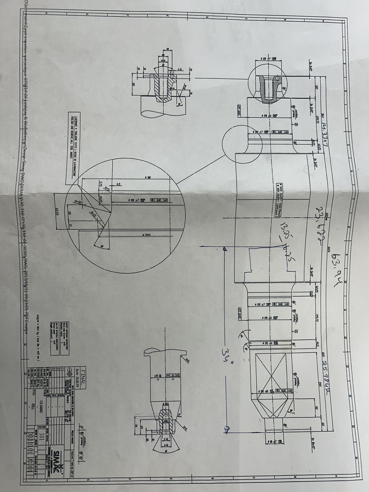
Working from supplied drawings on manual and CNC lathes: reading the drawing, planning the
operation sequence, selecting tooling and speeds and feeds, and inspecting in-process to hold
the specified tolerances.
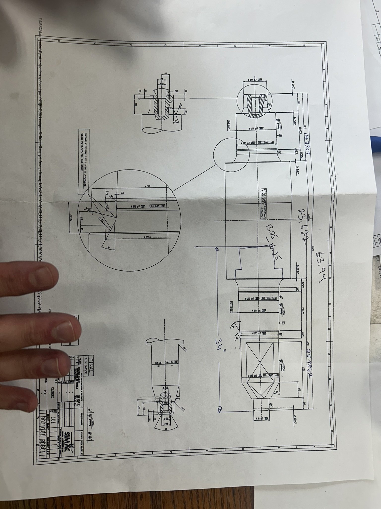
Drawings worked from
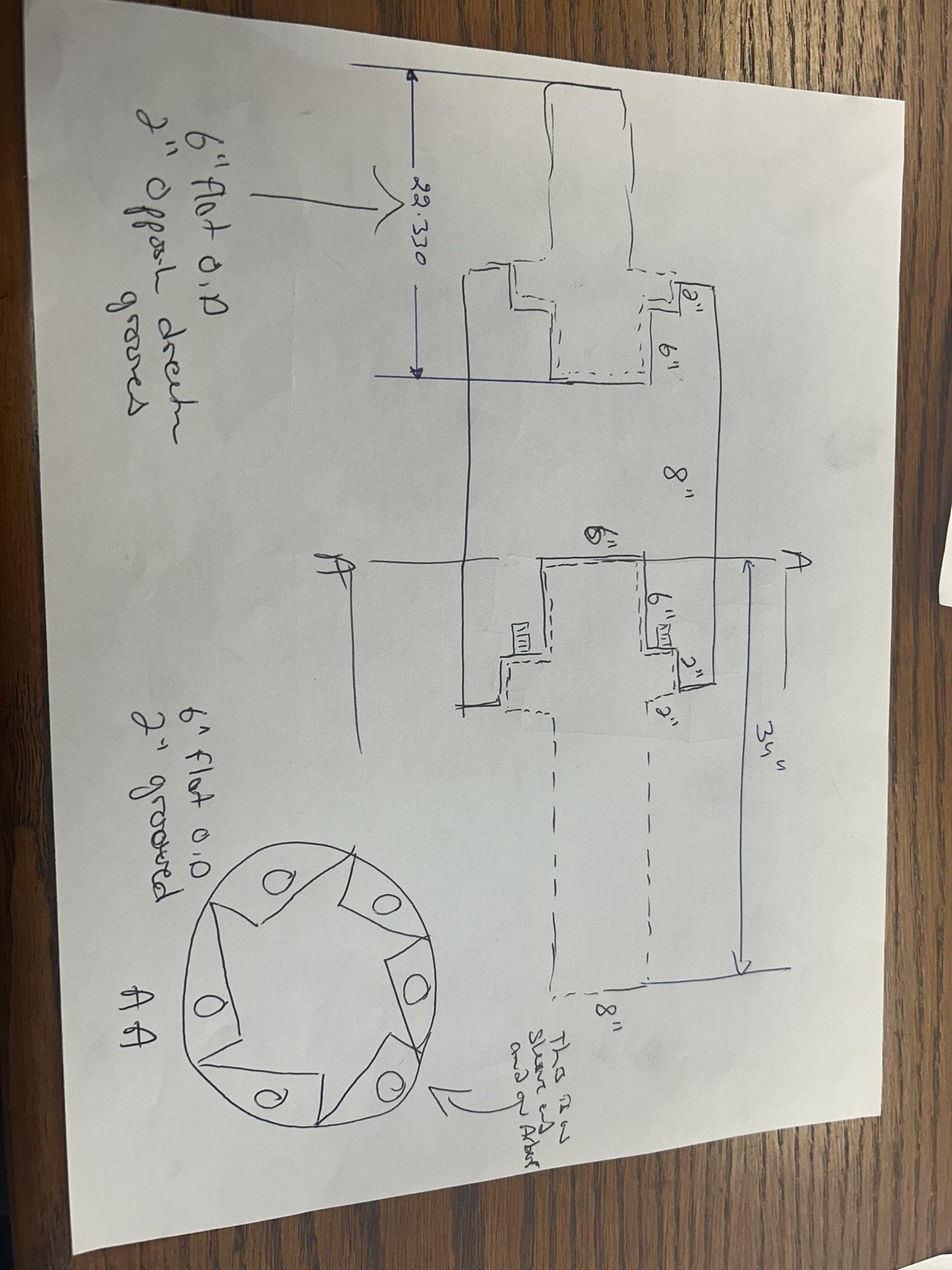
Supplied drawing on the floorDimensions and section detailSecond sheetHand layout of a turned profile
Parts machined to print
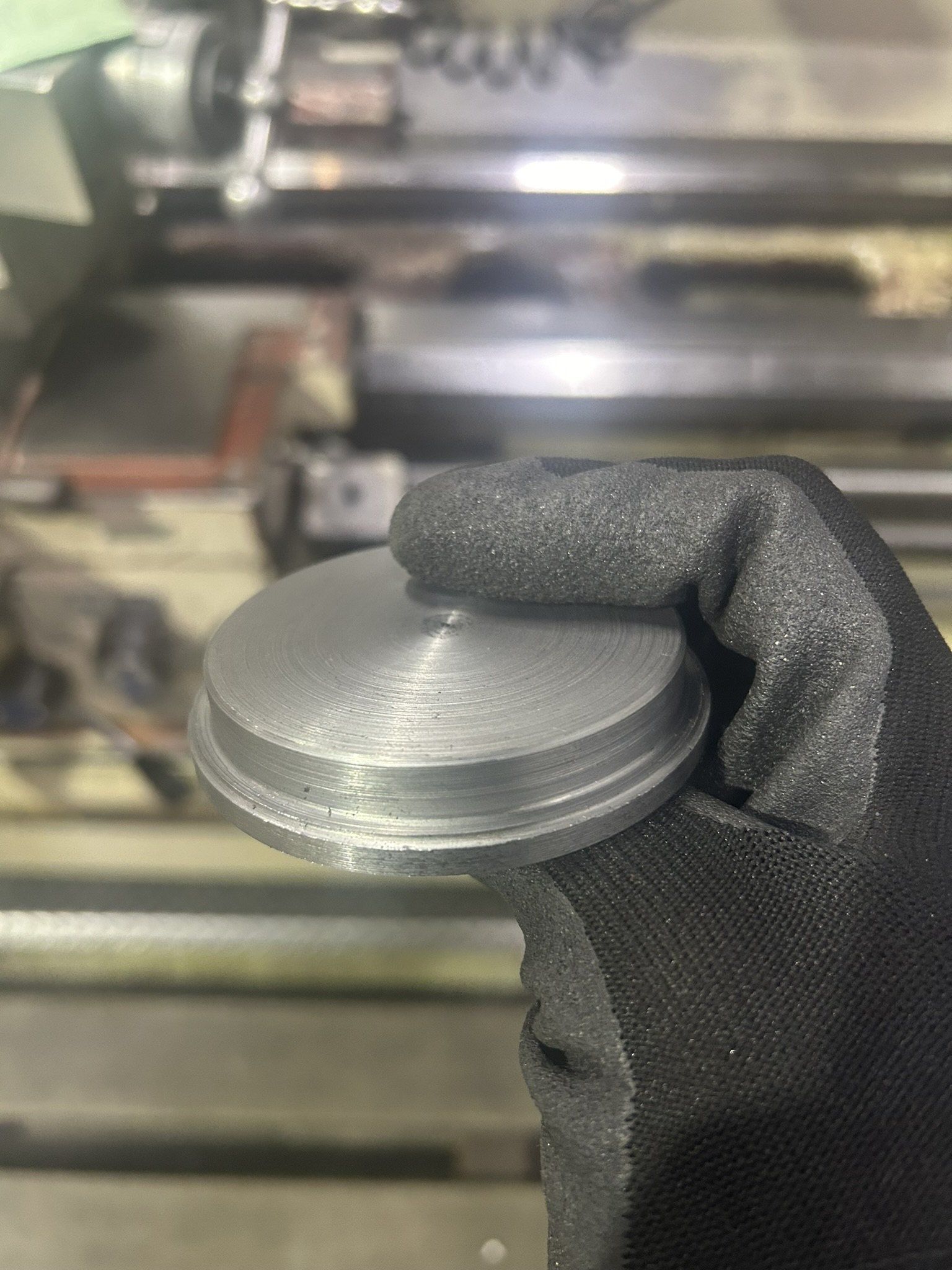
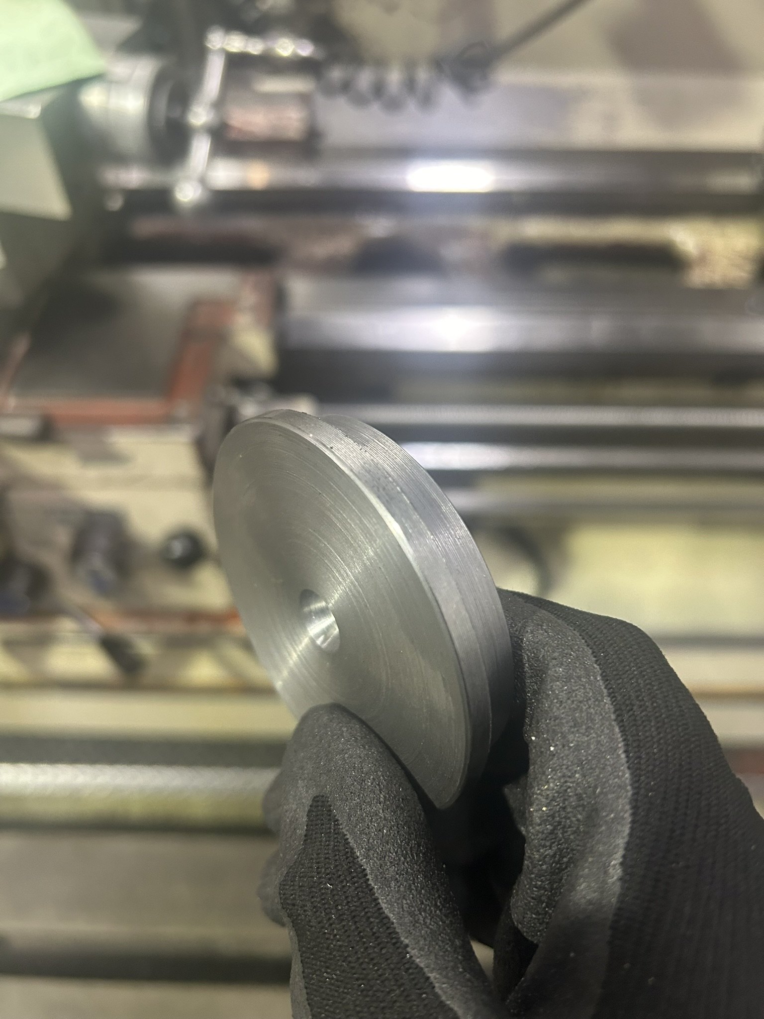
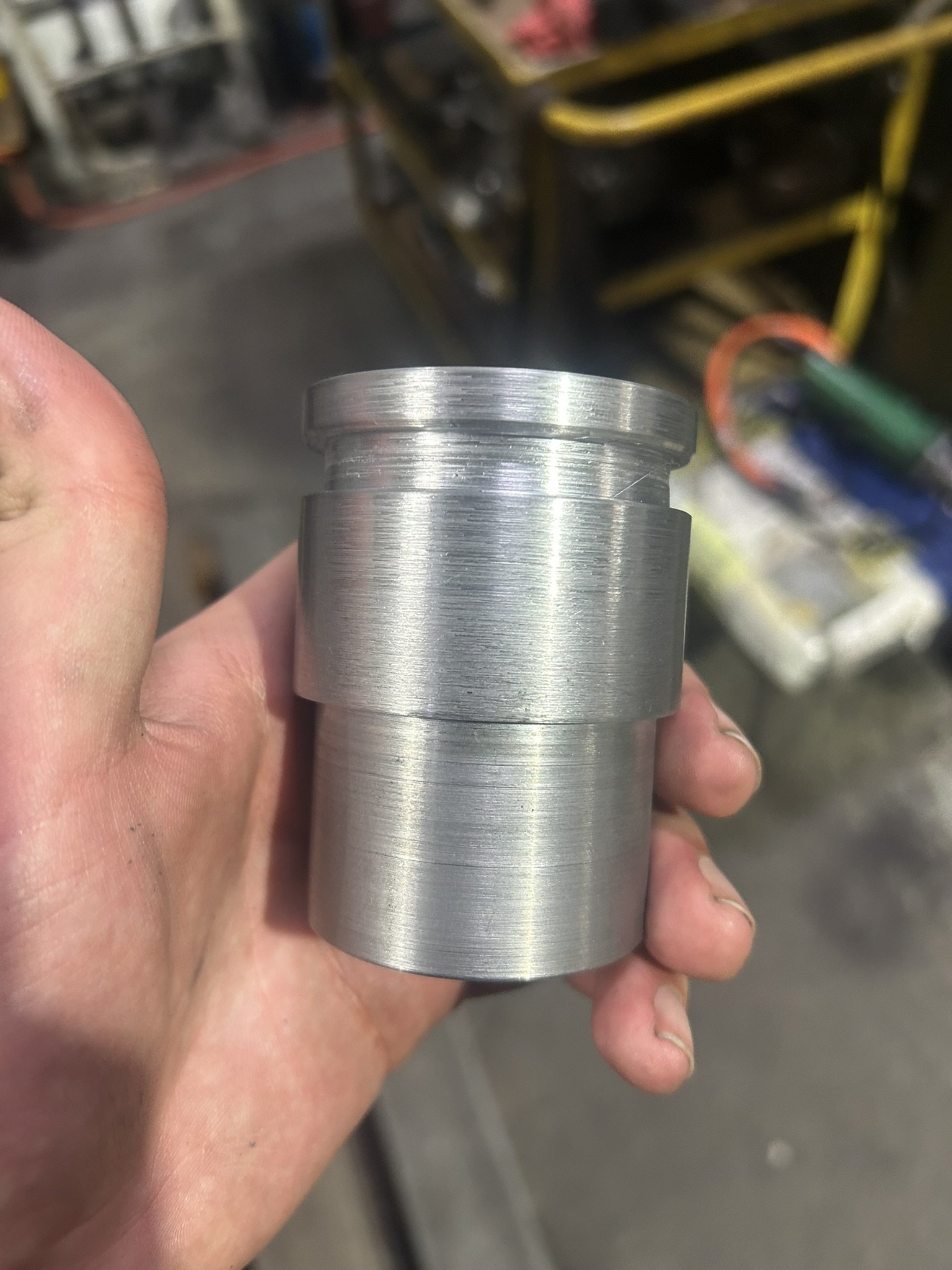
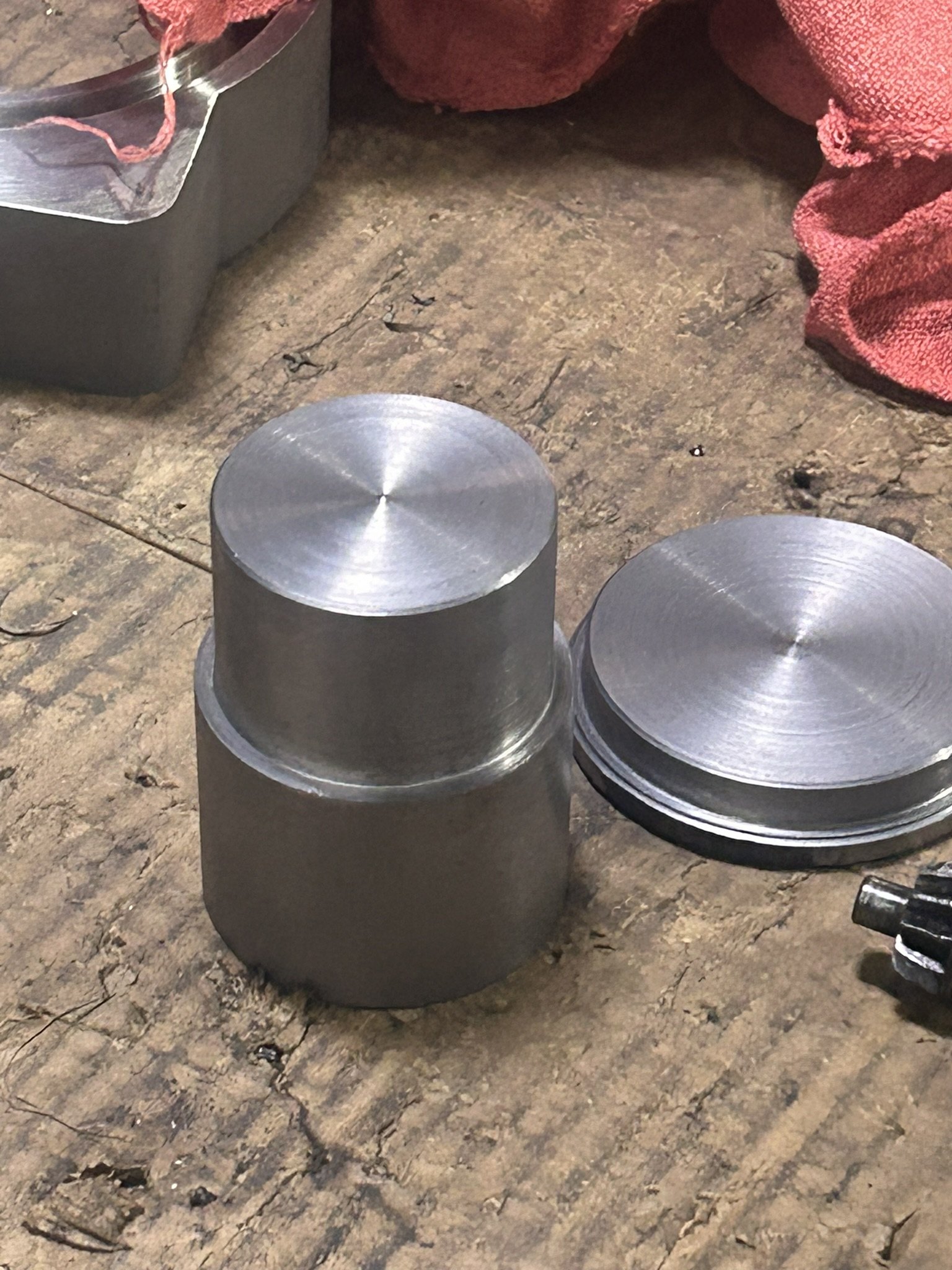
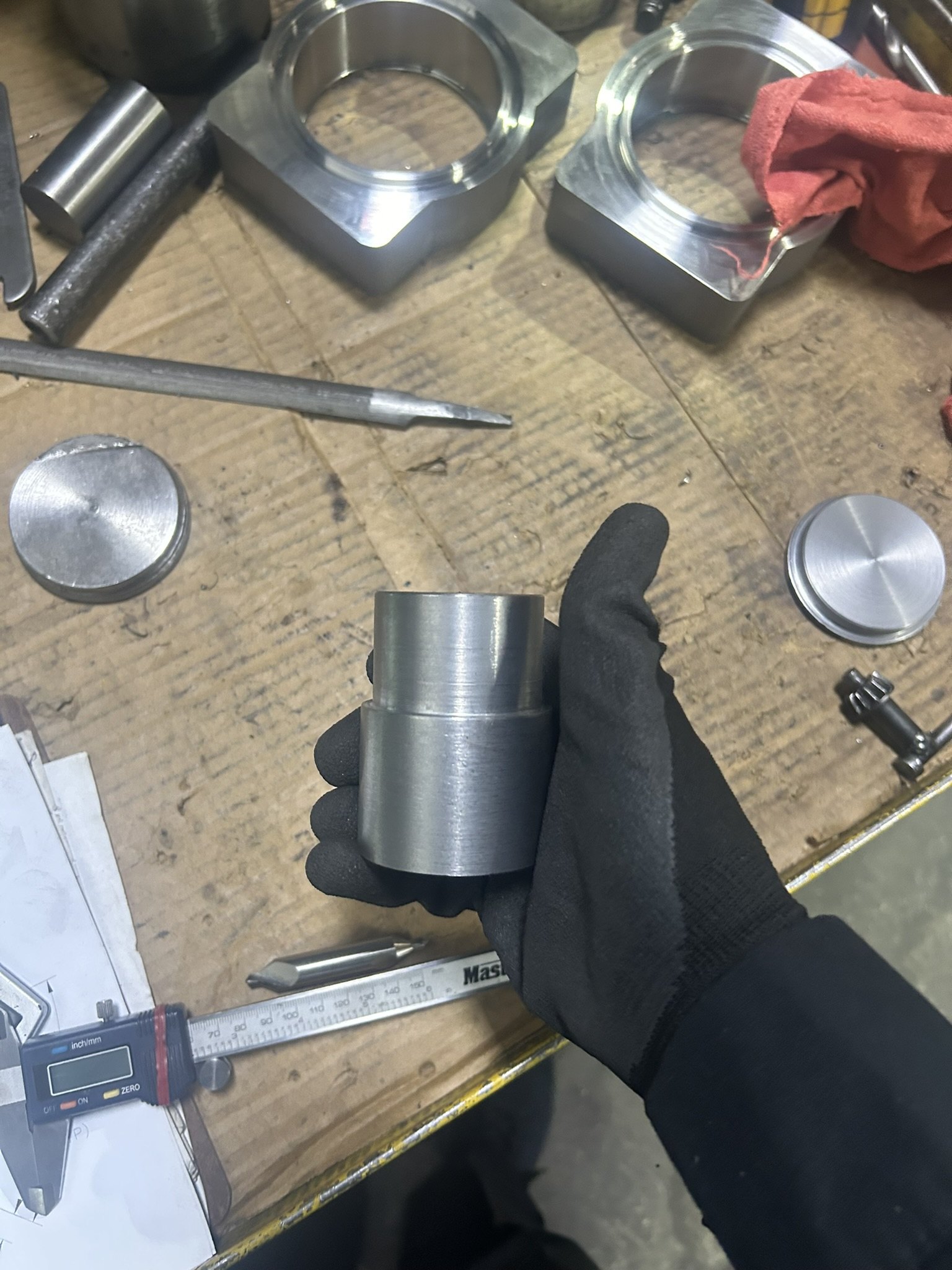
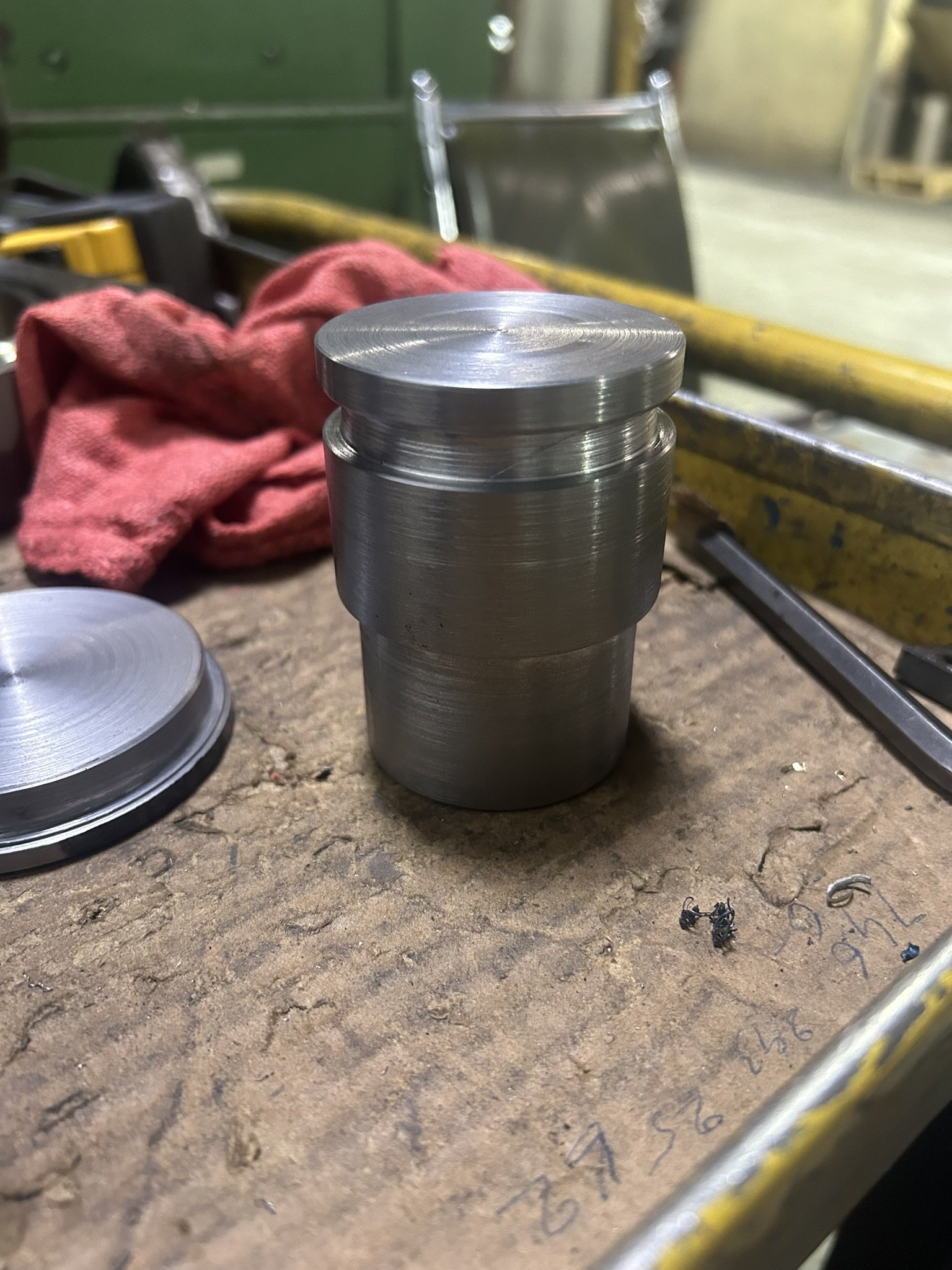
Grooved disc, straight off the latheEdge on — groove profile and turning finishStepped diameters turned to printFinished parts at the benchSecond pairPart off the machine
Quality engineering
Production Quality Control System
In daily use by 6 machinists · ~10 work orders per day · Shop-floor tablets
Bemco machines rolls and roll components for the steel mill industry to tight drawing
tolerances. Inspection was tracked on paper, where a measurement only got verified if someone
remembered to verify it. I designed and built the system that replaced it, now used by six
machinists on shop-floor tablets.

The workflow
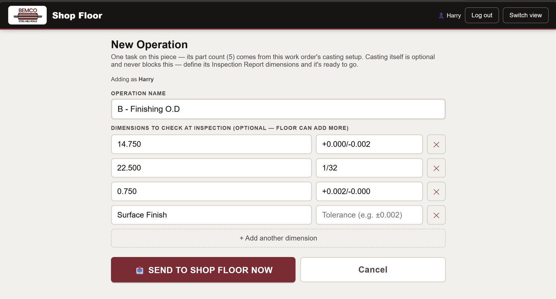
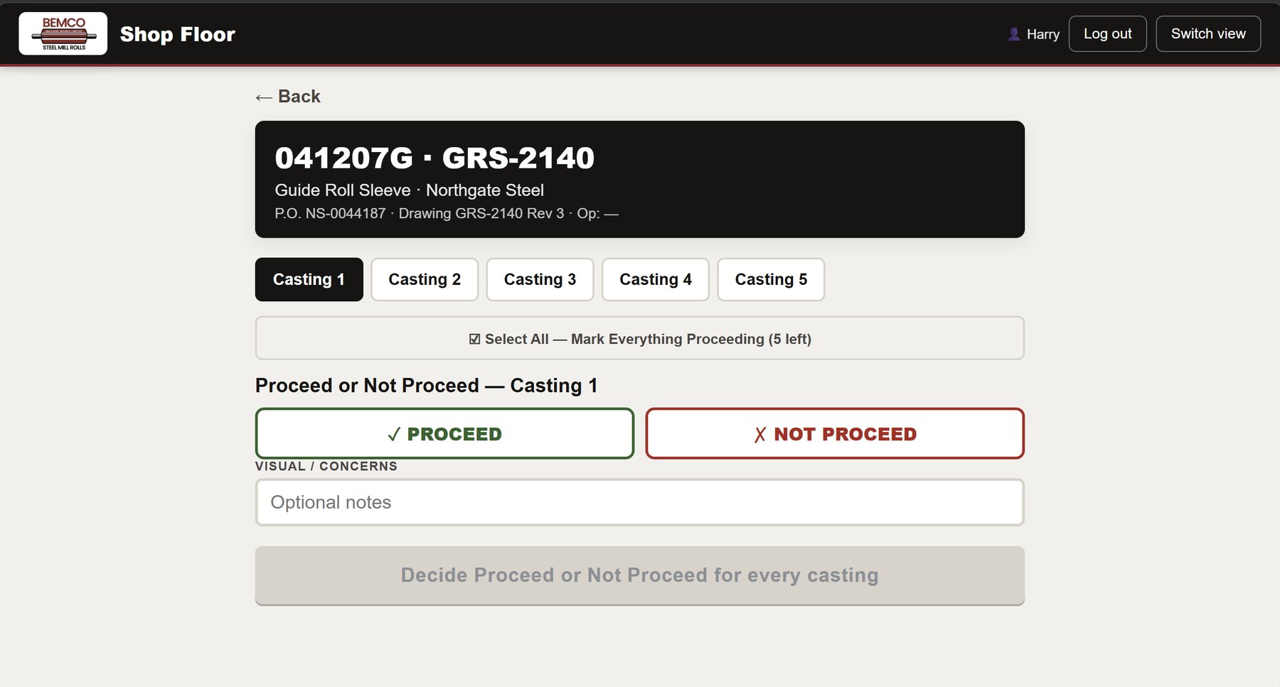
The office issues a work order carrying the customer, drawing number,
casting count, and the dimensions and tolerances for every operation. On the floor, each casting
is screened proceed or not-proceed before any machining time is spent on it. Operators then record
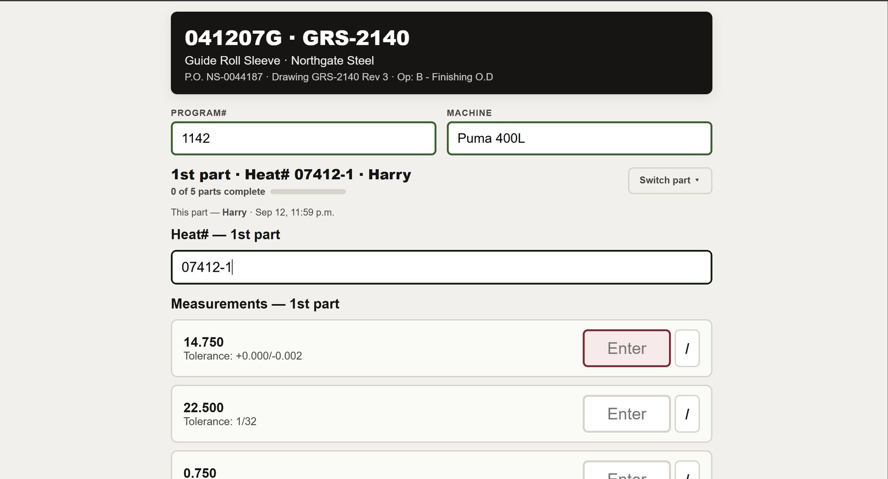
actual measurements against each dimension, checked against tolerance as they are entered.
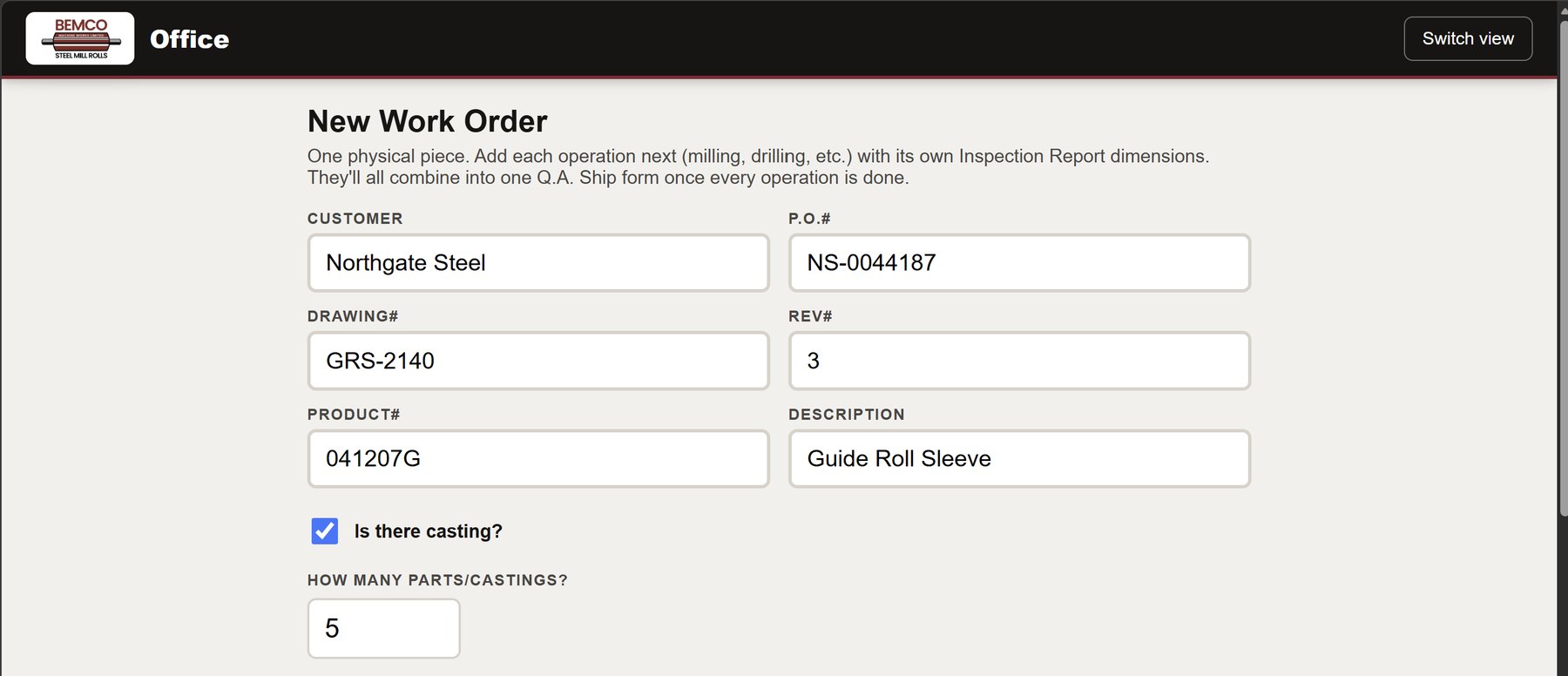
Three controls are enforced rather than encouraged:
each one is a rule the system applies, not a step someone has to remember.
Office to floor
Work order — customer, drawing, revision and casting countEach operation carries its own inspection dimensions and tolerancesCasting screened proceed or not-proceed before machining time is spentDecimal, fractional and angular tolerances checked as entered
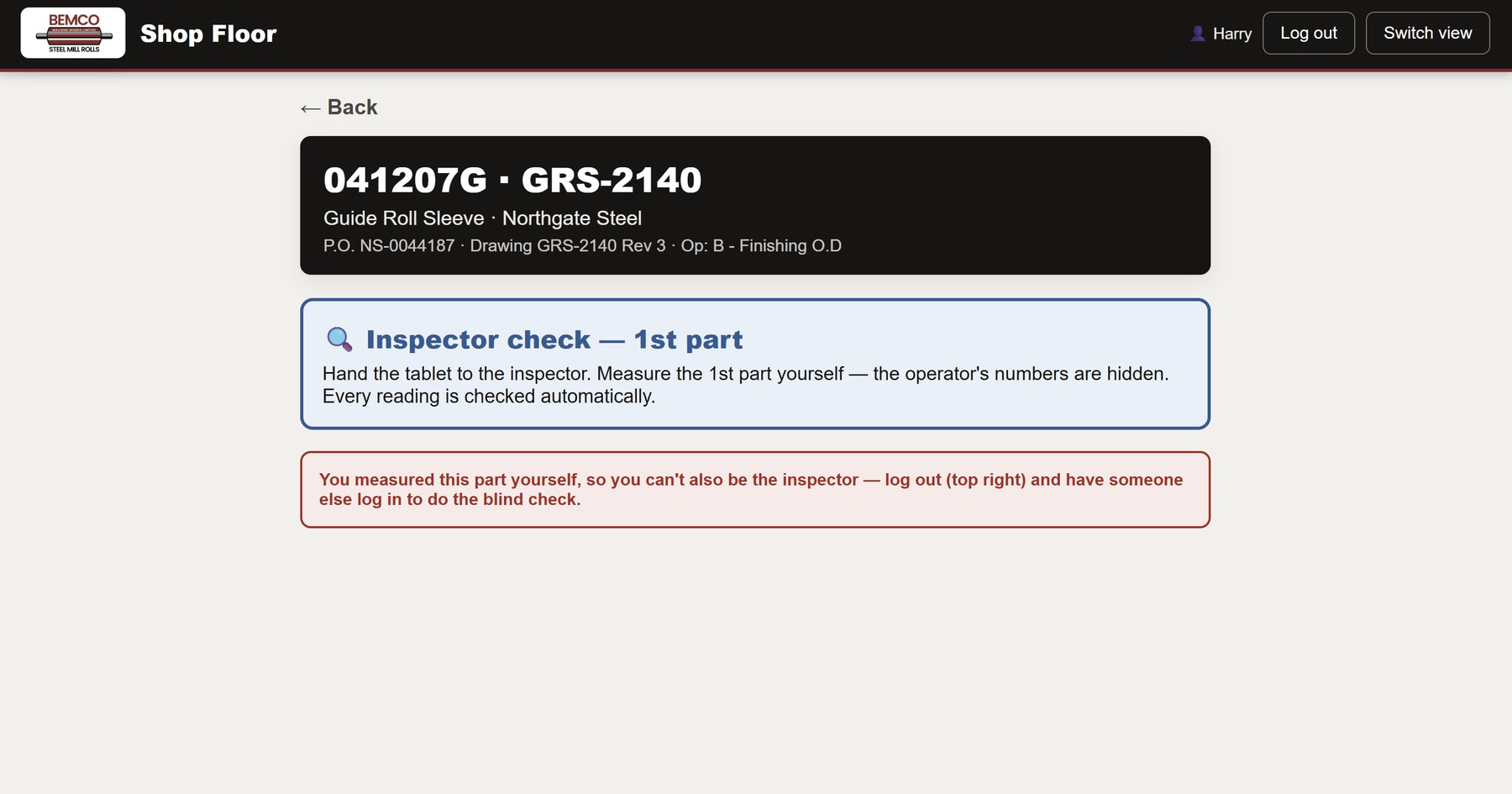
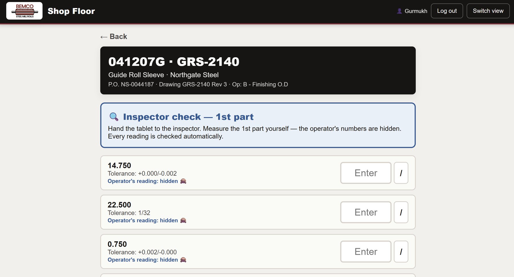
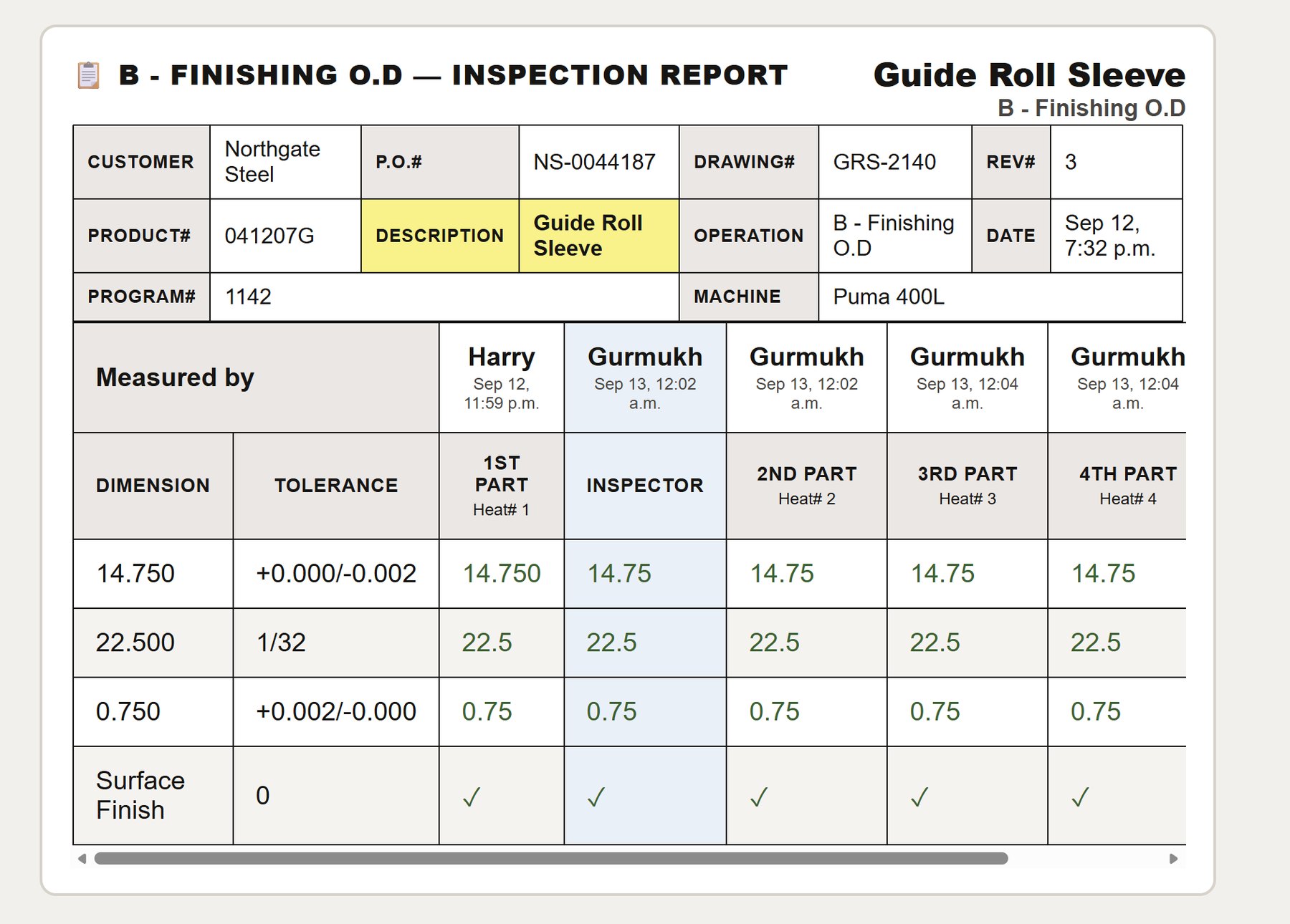
1 · Inspector check — the run stays locked after part one until a second person blindly re-measures it
An operator cannot inspect their own work. The system recognises who took the original readings and refuses the check.Blind re-measurement. The inspector sees the dimension and tolerance but not the operator’s reading.
2 · Non-conformance hold — an out-of-tolerance reading stops the operation
Caught on entry. A reading outside the band is flagged before it is committed.Hard stop. The operator must request an office override, which is approved or rejected and recorded.
3 · Sampling before shipment — and the record the customer receives
10% of parts, minimum one, randomly selected. A failure escalates the whole lot to 100% inspection.Inspection Report. Every part by name and timestamp, the inspector’s column beside the operator’s, each part traceable to its heat number.Write-once for operators, fully editable and printable by the office, giving a traceable history per part.
Screens shown use demonstration data.
The same system is covered from the software side under
Experience › AI & Software.
On-site build
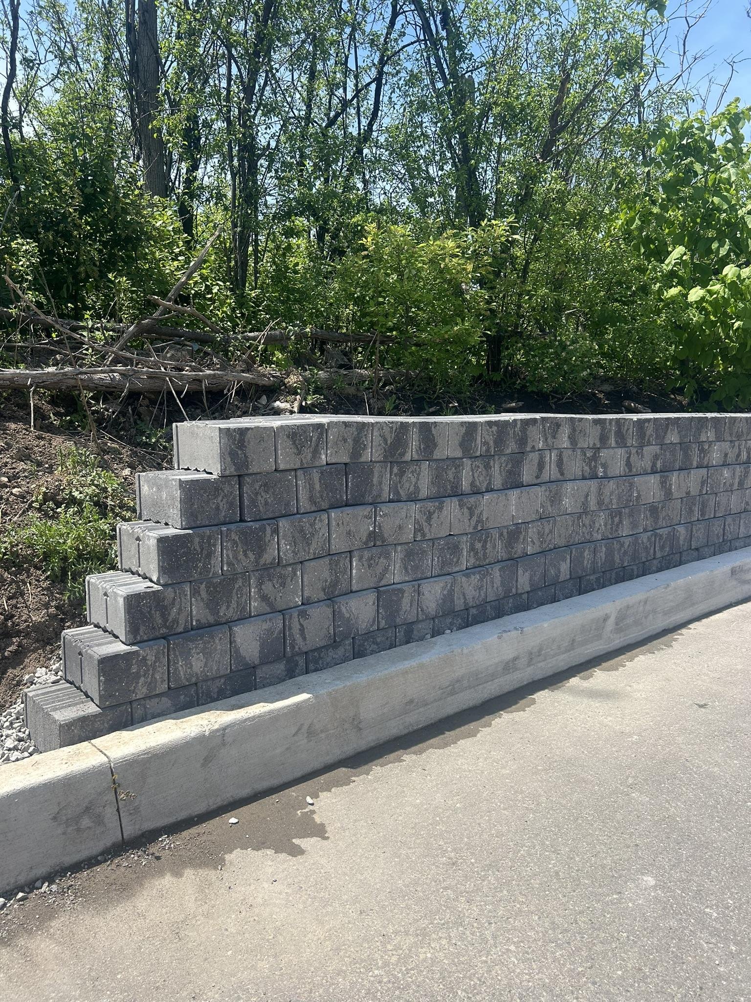
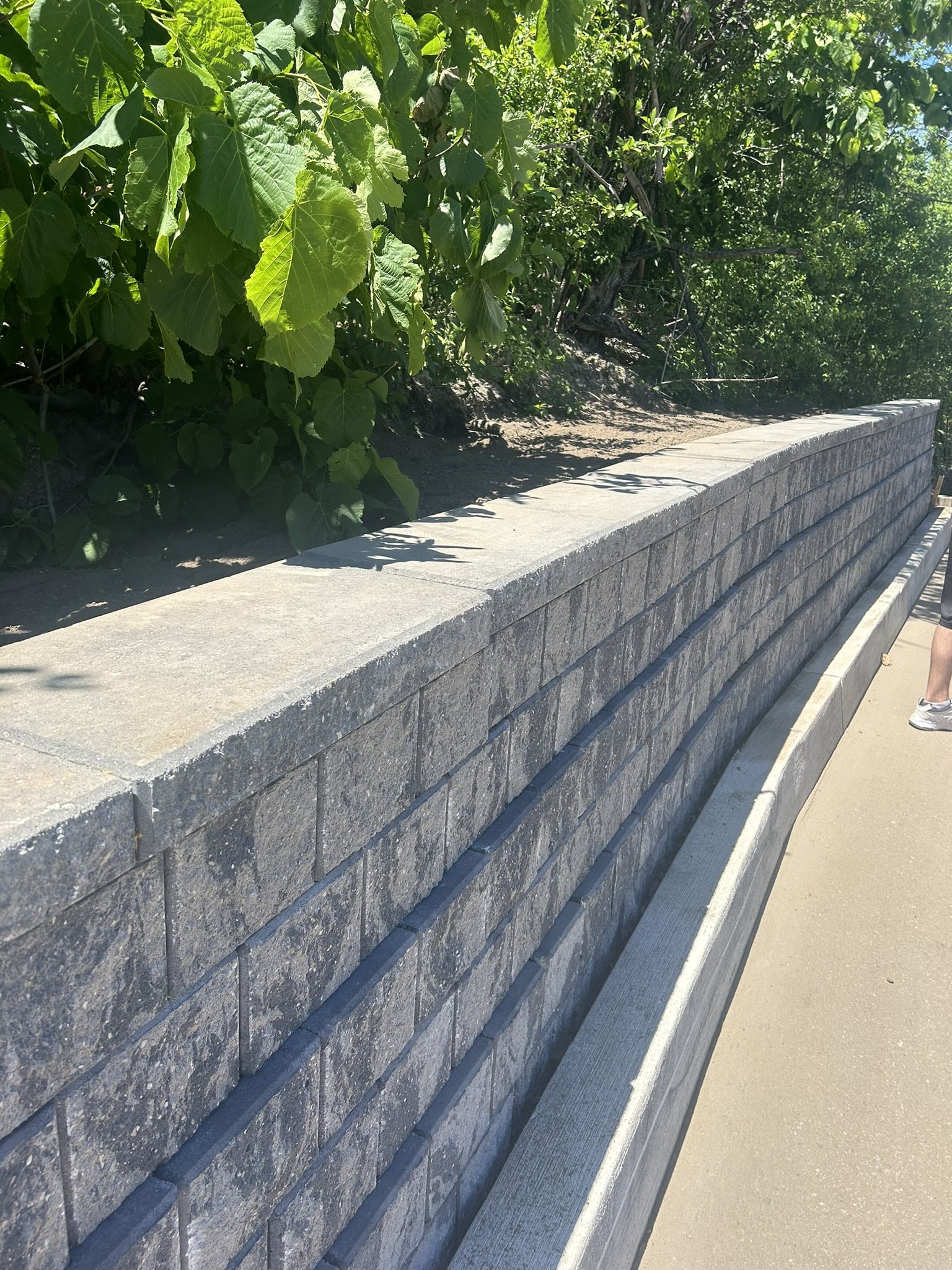
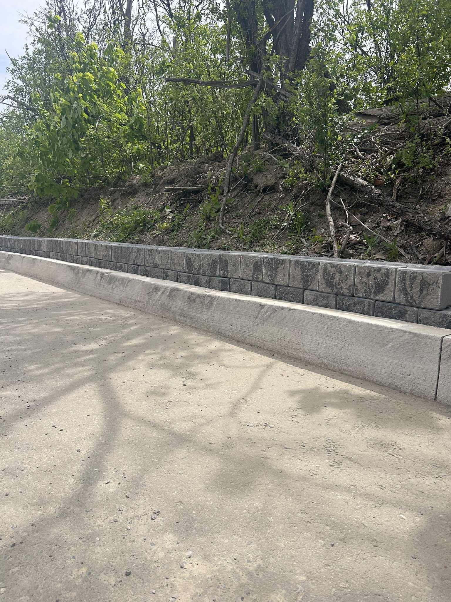
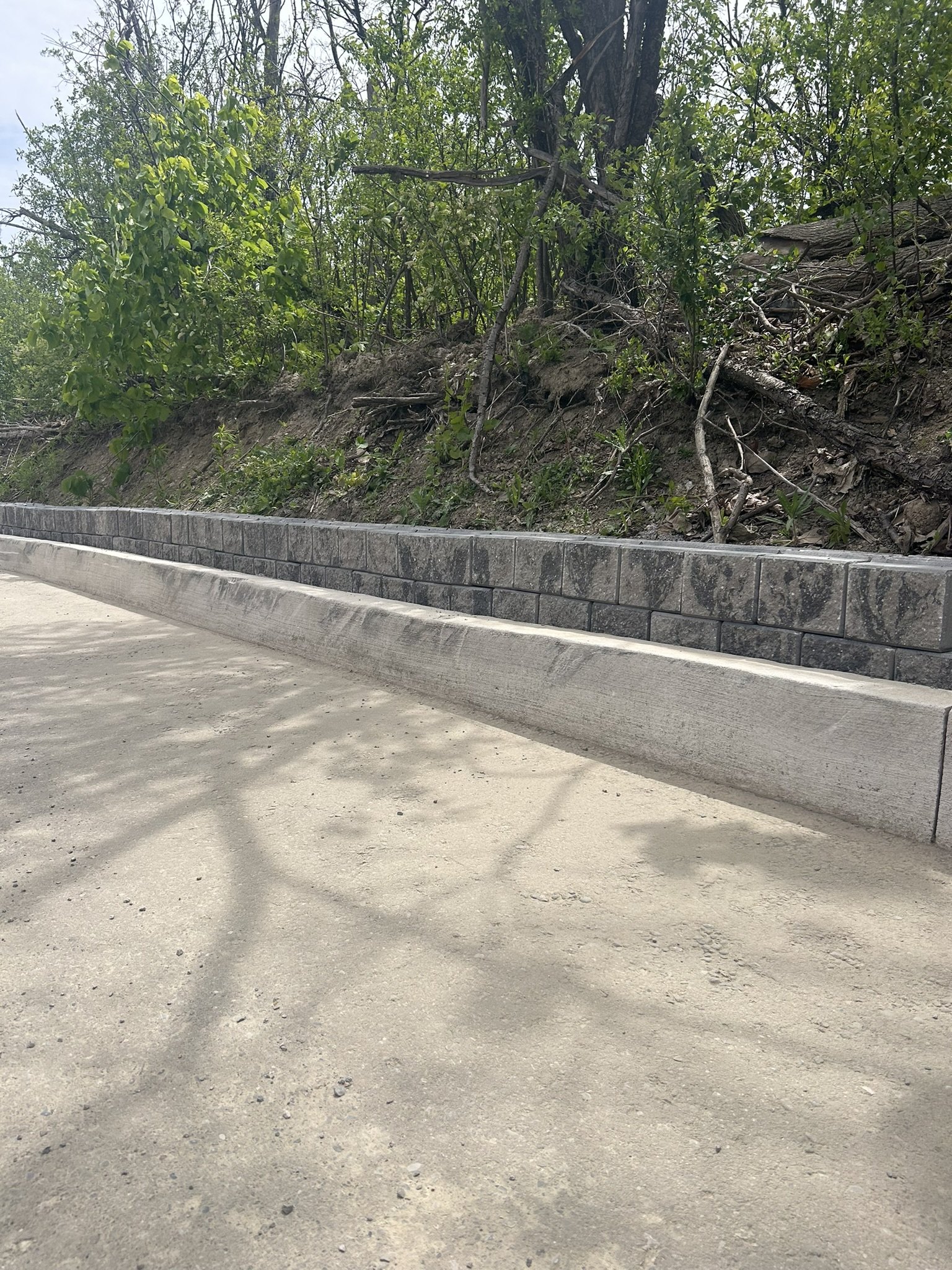
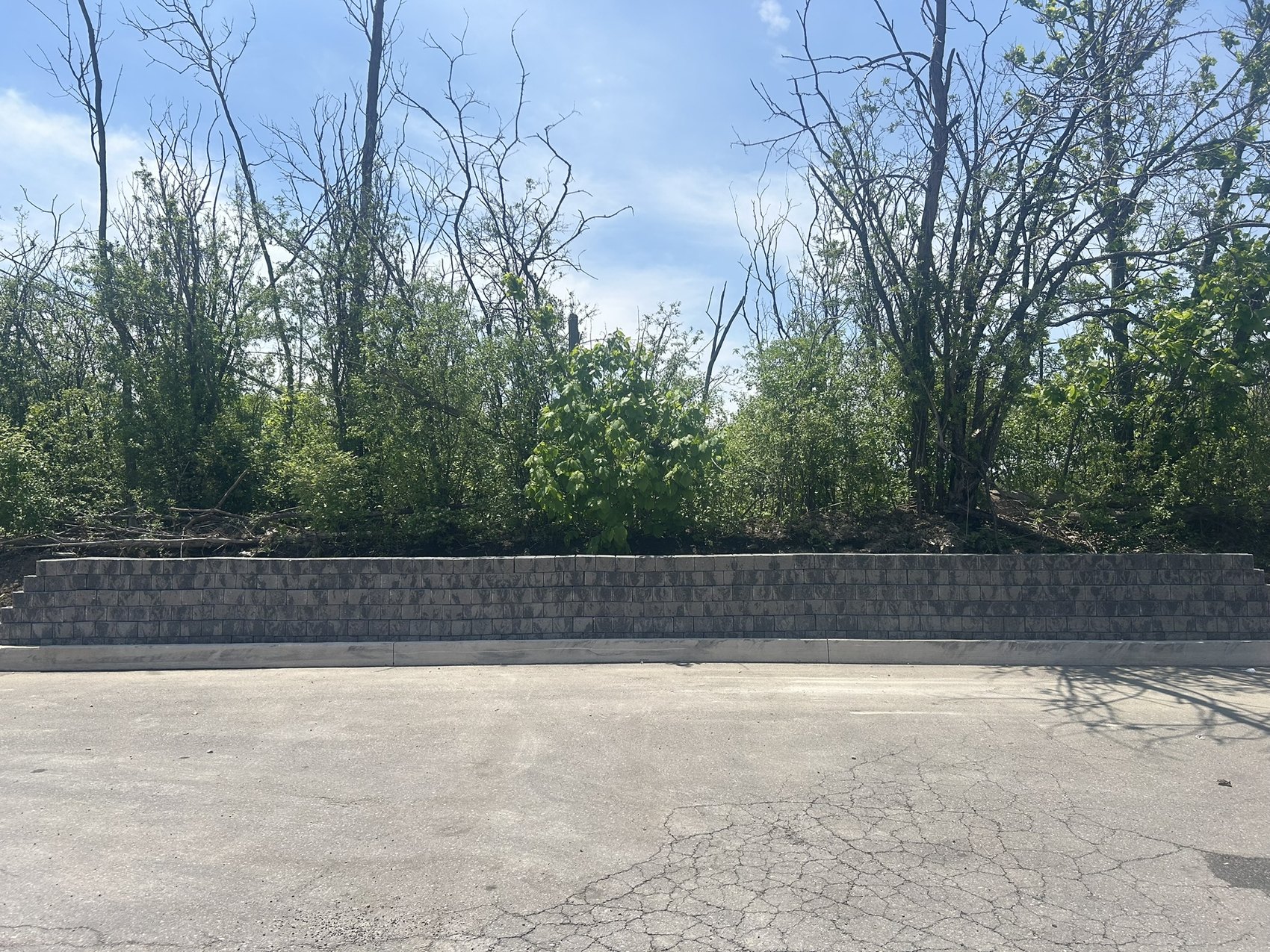
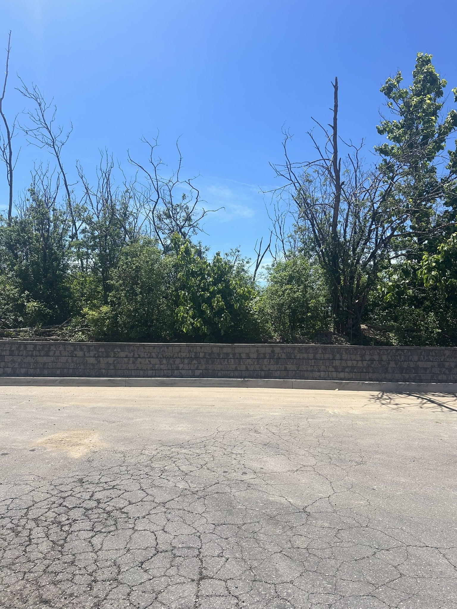
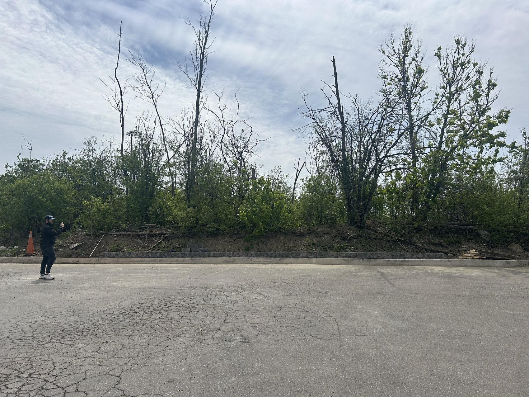
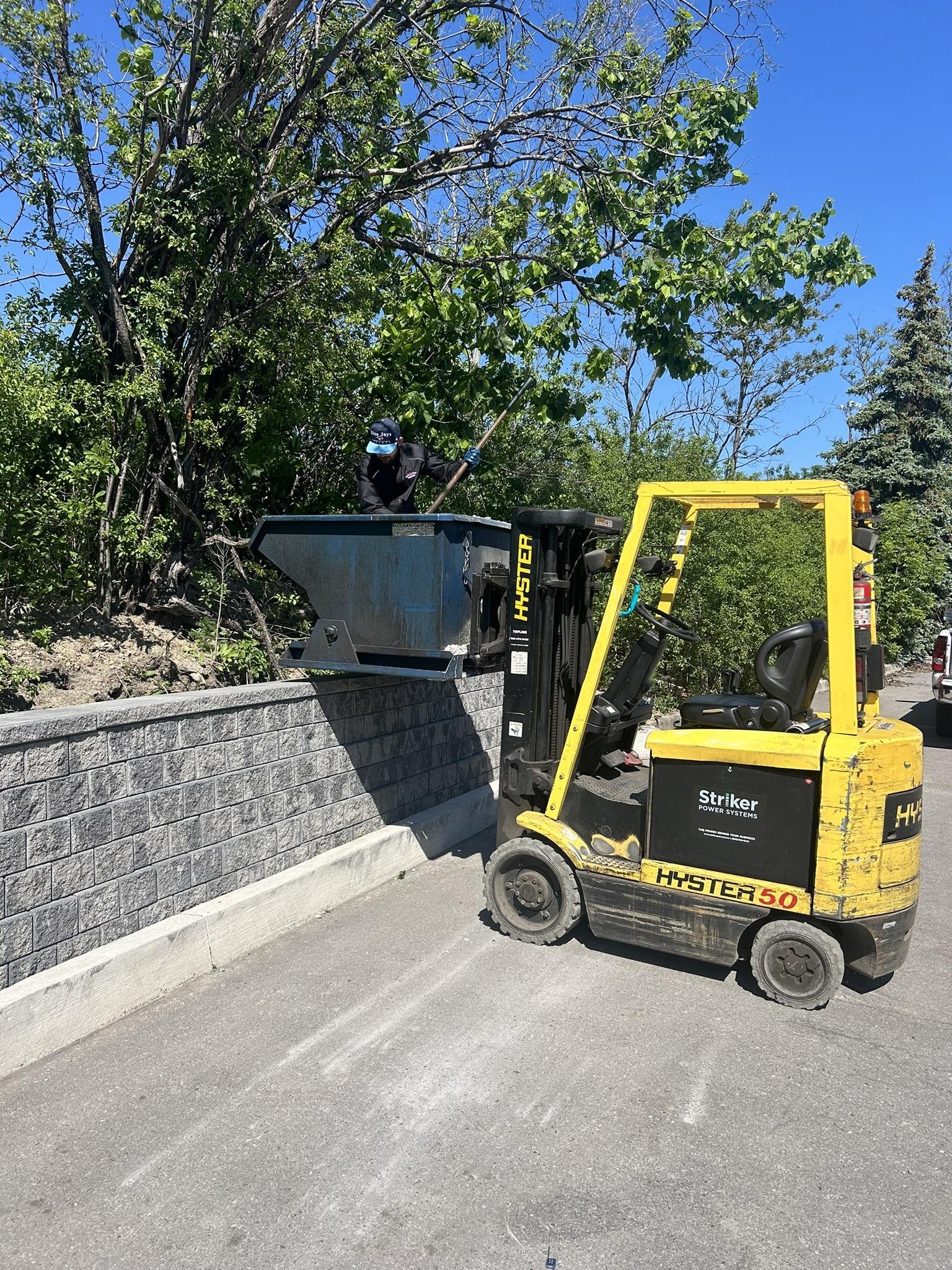
Retaining Wall
Layout · Excavation · Drainage · Material selection
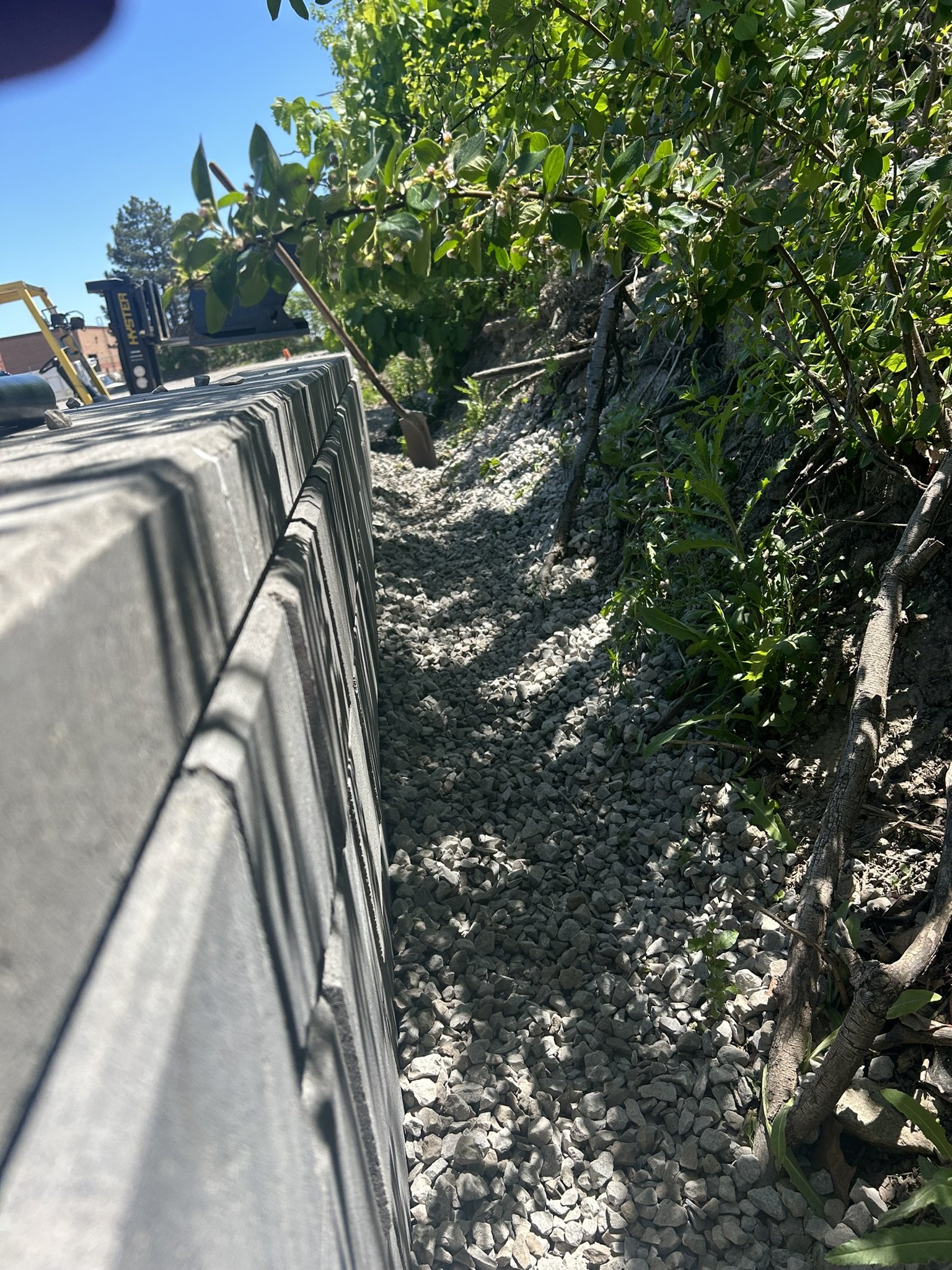
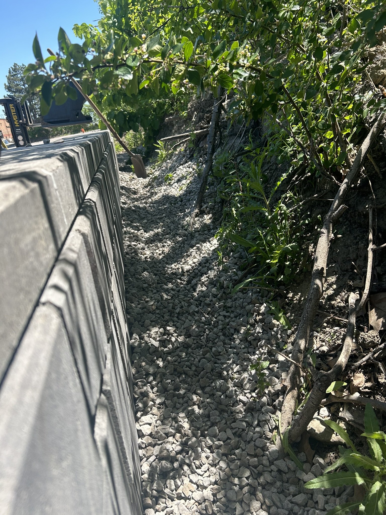
Designed and built a retaining wall sized to block falling trees. Base excavation proportioned
to wall height, gravel drainage layer to mid-height with drain pipe to relieve hydrostatic
pressure, and a setback every two courses to resist overturning.
Built on site
Moving block on siteSetback visible — each pair of courses steps back into the slopeAlong the slopeDrainage sideFinished runFull lengthFrom the yardLooking back along the finished wallFull run from the far endSite before the wall
Front Suspension Team (1st Place Overall OktoBAJAfest)
Baja SAE, Western University · London, ON ·
Sept. 2025 – Present
Conducted design and manufacturing of the front suspension for an SAE Baja off-road vehicle
by independently researching manufacturing methods and design trade-offs under competition
constraints.
Improved prior suspension design, contributing to 1st place finishes in Hill Climb
(15.72 s), Short Track (24.32 s), Baja Cross (79.07 s), and Endurance under varied dynamic
loading conditions.
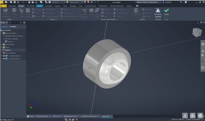
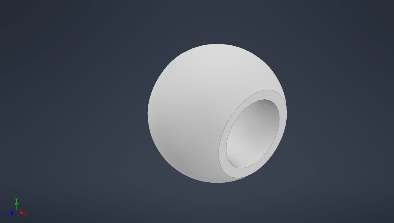
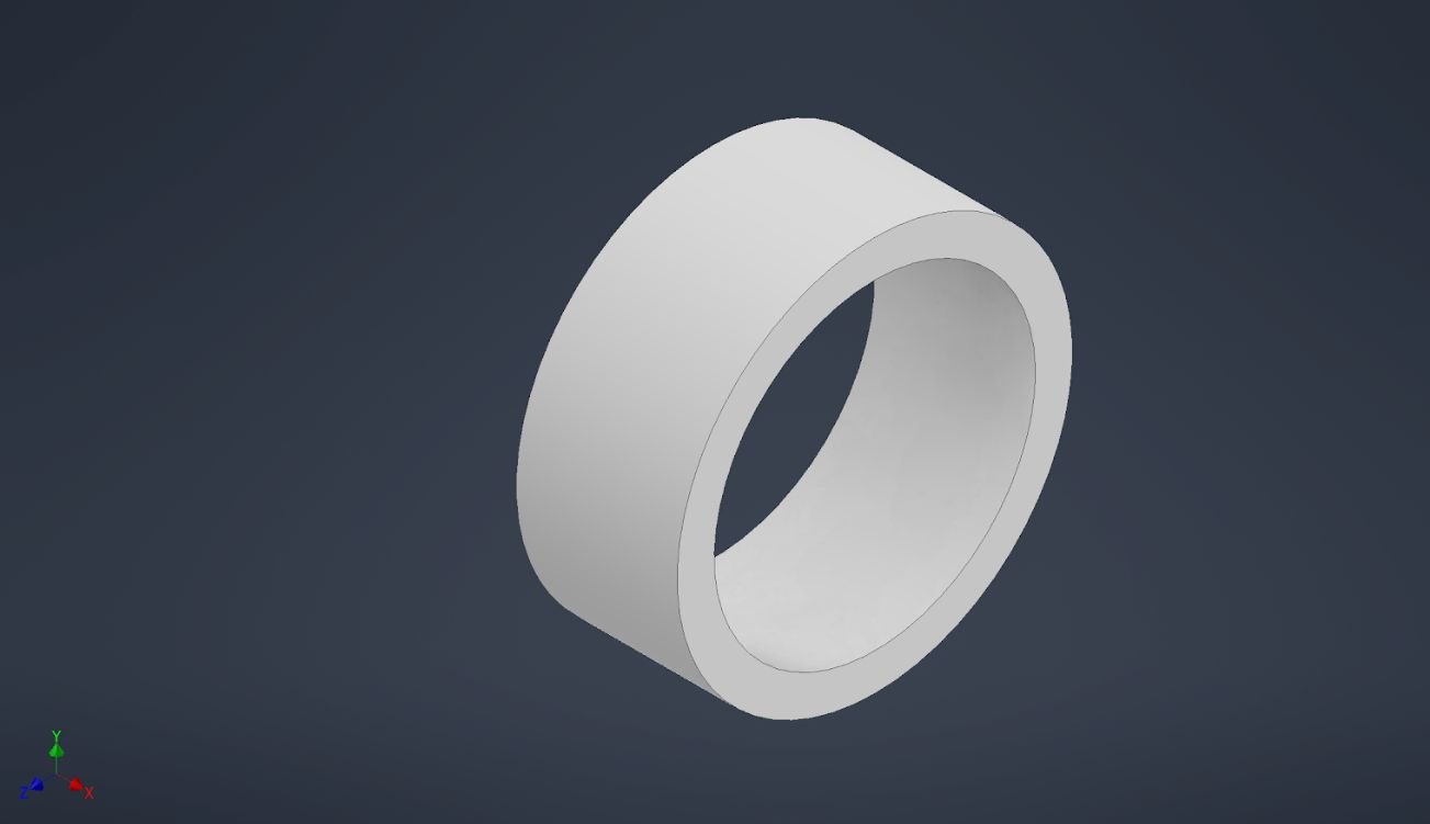
Redesigned and modeled suspension components in SolidWorks, including the spherical plain
bearing (uniball), conducting iterative design refinement to optimize strength,
manufacturability, and assembly integration.
Uniball modelling
Outer raceAssembly constraints in Autodesk InventorSpherical ball, allowing multi-axis articulation